UID verifier lights Data Matrix codes
Direct part marking (DPM) is used in the automotive, aerospace, and defense industries to identify and trace products in the manufacturing process. Two-dimensional (2-D) Data Matrix codes containing a manufacturer identification number, the serial number, and often the part number are placed on these parts in several ways, including laser etching, dot peening, and chemical etching. Because of the built-in redundancy embedded in the 2-D Data Matrix code, marked parts can be read after multiple manufacturing steps or in case some mechanical part deformation may have occurred during manufacturing.
Four key elements are required for DPM applications: marking, verification, reading, and communicating the results. To guarantee that these marks can be read throughout the entire production process, manufacturers use verification to help them strictly comply with mandated unique identification (UID) standards such as the US Department of Defense MIL-STD-130. This standard ensures that a sufficiently high-quality 2-D Data Matrix mark is produced such that, even if the mark is subsequently damaged, it can still be read by a variety of readers throughout the life span of the product.
“MIL-STD-130 requires that military contractors supplying a product with an acquisition value greater than $5000 or a component that is mission critical or serialized must mark their products with a specially formatted 2-D Data Matrix code,” says John Agapakis, machine vision business manager at Siemens Energy & Automation (Norcross, GA, USA; www.usa.siemens.com). “This standard mandates more than just part marking. It also specifies how, once marked, products with a UID code must be verified and validated to ensure that the mark is readable and formatted correctly.”
To do this, the latest version of the standard, MIL-STD-130N, specifies a number of different lighting methods that must be used to grade the quality of direct part marks and the specific mark quality measures that must be presented by defense contractors when delivering parts to the government. The reason for this is simple. While it may be relatively easy to read a flat laser-marked metallic part using on-axis illumination, it may be more difficult to read and verify other marks using the same type of illumination.
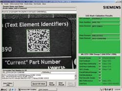
Thus, to properly verify a direct part mark, the 2-D Data Matrix code must be verified using several lighting conditions and mark-quality measures. These include cell contrast, print growth, axial nonuniformity, grid nonuniformity, unused error correction, cell modulation, fixed pattern damage, minimum reflectance, reference decode, and cell size, which are computed for each lighting geometry. In the current MIL-STD-130N specification, ten types of lighting are specified, all using red 650 ±20-nm LEDs.

To verify marks on curved surfaces, a dome light is required, as specified in the Association for Identification and Mobility (AIM; Warrendale, PA, USA; www.aimglobal.org) DPM-1-2006 specification, an illumination method excluded from the previous release of MIL-STD-130. The dome light has been incorporated in the just-released MIL-STD-130N specification. To meet these rigorous specifications, Siemens has leveraged its expertise in machine vision lighting, smart cameras, optics, and software in the design of its UID Compliance Verifier DPM developed to verify direct part marks.
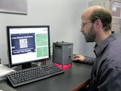
At a recent demonstration, Agapakis described how the unit has been designed to comply with both the MIL-STD-130N and AIM DPM-1-2006 verification standards. The unit allows ten illumination methods to be used to test each part. This is done by combining a 90º on-axis light (DOAL), four quadrants of linear red LEDs angled at 45º to the mark under test, four quadrants of linear red LEDs angled at 30º to the mark under test, and a diffuse dome illuminator. These behave like the company’s patented Cloudy Day Illuminator (CDI). To achieve the ten illumination methods, the LEDs are sequentially switched using the DOAL, CDI, both arrays of the angled LEDs, twin (north/south, east/west) quadrants of the 30º LEDs, and single (north, south, east, west) quadrants of the 30º LEDs.
To control the operation of these lights, the unit uses a version of the company’s HawkEye smart camera. This supplies I/O capability to switch the lights in sequence with software running in the camera’s embedded processor. “Part geometry, the type of marking, the type of surface, and the material used are all important factors that need to be considered when verifying a direct part mark,” says Agapakis. “This latest DPM verifier design removes the burden from the operator and does it automatically, with the push of a button.”
For example, while a flat laser-marked part may have more contrast when illuminated with a DOAL, a cylindrical part requires CDI. For this reason, the recently released MIL-STD-130N specifies that direct part marks be inspected under multiple lighting conditions.
To ensure the operator locates and positions the mark correctly, the company has also developed custom user-interface software to help align and position the 2-D code. This symbol orientation ensures compliance with the MIL-STD-130 and AIM DPM-1-2006 standards, which require the symbol to be in the center of the field of view and oriented such that the horizontal lines in the symbol are parallel with a line formed by the edge of the image senor to within ±5º.
After the mark is correctly placed, images are captured under multiple lighting conditions and the quality and syntax of the mark are determined. Results are then transferred from the unit’s embedded smart camera over Ethernet to a PC display. Here, the operator can see the results of each test and the quality grade of each mark. The data are displayed in a form that can be printed and supplied to government agencies or archived for quality records.
“Of course,” says Agapakis, “the mark may not be verified under some lighting conditions. However, as long as one of these illumination methods can verify the mark, the part can be delivered to the government by the contractor. While it is relatively easy to read such marks using a number of hand-held readers, it is far more difficult to quantitatively verify their quality in the proper fashion.”