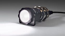
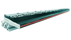
3-D laser triangulation system with FPGA-based camera checks critical dimensions during production of multilayer pipes
The building-materials industry is just one industry affected by today’s rising commodity prices. As the price of aluminum and other raw materials increases, product designers are finding new ways to build better products, using less or composite material. Recently, Templet, a multilayer composite pipe (MLCP) manufacturer, turned to industrial quality inspection specialist Fortec Forschungstechnik to develop an automated nondestructive and contactless measurement system to assist in the formation and welding of multilayer pipes used for plumbing and cooling applications.
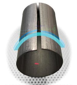
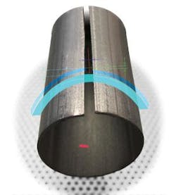
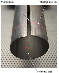
To keep costs to a minimum while delivering high-speed inspection, Fortec uses an OEM CMOS camera from VRmagic with a laser line generator and image-processing software package from reverse-engineering specialist Knotenpunkt. When combined with a industrial touch-panel PC, the Fortec GO 3-D laser-triangulation inspection system with Xilinx field-programmable gate array (FPGA) can verify and inspect up to 100 m of multilayer tubing per minute prior to welding, reducing conditions that would result in yield losses from poor welds or inadequately formed multilayer tubing (see Fig, 1).
MLCP trumps traditional pipe
MLCPs are constructed using a polyolefin core (inliner) that is coated with a special adhesive material. As a gas barrier, aluminum tape with thickness ranging between 0.1 and 1 mm is cut to specific width and molded around the adhesive coated core. The tape must be trimmed so that when molded around the core a specific gap remains.
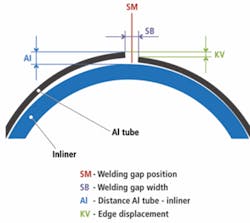
If the gap is too large, out of position, or one edge of the tape is out of position, the tungsten inert gas (TIG) welding in the next manufacturing step can damage the core; if the gap between aluminum and inline core is too small, the aluminum tape may not bond sufficiently, while the adhesive is burned. After the TIG weld, the tube is coated in a final set of polyolefin and adhesive and then heated to bond the various layers together.
This approach to tubing offers several advantages over galvanized and even copper pipes used to carry liquids and coolant for condensing operations, including
- no corrosion or deposits
- low weight
- neutral to water quality
- easy installation because it does not require soldering, as does copper
- low force bending
- low thermal expansion
- and, most important, improved cost-benefit ratio for end users.
Because of these benefits, the use of MLCP is growing in Europe significantly, particularly in Eastern European countries.
The manufacturing process begins with extrusion of the polyolefin inliner. In a single-step inliner-production process, the extruded inliner is immediately wrapped by the aluminum tape. To produce stronger bonds, the polymer inliner is rolled and specially treated (that is, radiated) to produce chemical combinations between polymer molecules and further strengthen the inliner material.
The MLCP production process runs endlessly. Therefore, an accumulator is necessary when aluminum rolls and/or inliner rolls are ending and need to be changed. Based on the specified diameter of the tube, the aluminum tape is cut to the right width, a separate winder collects the scrap that is removed, and the remaining cut tape is brushed to clean the edges, remove any burrs left by the cutting operation, and most importantly, to condition the aluminum-tape surface for good adhesive properties.
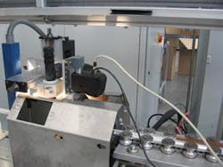
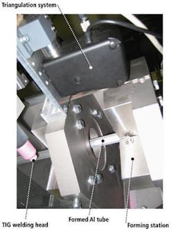
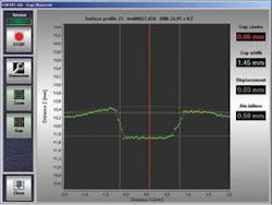
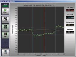
The polymer tube and aluminum tape are then fed into the tube-forming machine. The polyolefin tube is coated with an adhesive and then wrapped by the aluminum tape through a set of rollers. After the forming step, and directly before the welding step, the Fortec GO system inspects the tube for proper diameter, gap properties, and gap position (see Figs. 2 and 3).
null
null
FPGAs and lasers
The Fortec GO was designed to add noncontact distance inspection capabilities to new and existing manufacturing lines. Because so many 3-D machine-vision applications are retrofits, Fortec decided to use FPGAs on the camera to provide relatively inexpensive image processing on the camera and enable low-frequency data transmission back to operator/HMI, which may be some distance away. “By using USB 1.0 with a 64-Mbyte ring buffer to prevent frame drops, the Fortec GO can be placed up to 45 m away from the industrial panel PC,” explains Fortec’s Karsten Lothar Feiste.
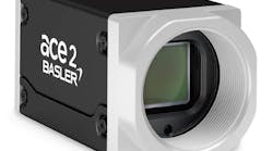
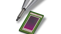
Using low-frequency transmission, costs and heat generation are kept down, according to VRMagic’s director of public relations Meike Hummerich. The VRmFC-x series of FPGA cameras is a line of cameras designed to support various OEM needs, including USB compliance up to 2.0 and FPGAs from 400,000 gates to 1.5 million gates. The Templet application uses a 754 × 482-pixel sensor with global shutter so that images of the tubes moving at speeds up to 66 mm/s do not contain blur that would confuse the Bayer, binarization, and subsequent triangulation algorithms.
Using Xilinx ISE software to program the 400,000-gate FPGA, VRMagic has developed several basic image-processing routines relevant to 3-D inspection, including Bayer filters for binarization and run-length encoding lossless compression—a compression method particularly suited for binary images. A small microprocessor and associated electronics can then focus on communication protocols, such as USB, while a built-in server software provides TCP/IP over either USB or Ethernet ports for remote access and monitoring of the inspection system. “The use of an FPGA-based camera compared to a traditional frame grabber is more cost-efficient and lessens the image-processing demands on the industrial PC’s CPU,” explains Feiste.
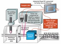
In the Templet application, preprocessing is done on the camera, and the binary image is communicated via USB 1.0 to the industrial panel PC. The PC runs the 3-D triangulation routines and Fortec’s API, which analyzes the tube formation, relevant gap properties, and the gap position. The PC communicates with the PLC through a proprietary digital I/O box developed by Fortec to send an alarm and stop order to the tube-forming machine in the event a parameter falls out of specification. Also, the PC offers Ethernet connection to the LAN. Through the Ethernet connection, external applications and data bases can store the analyzed forming properties and use them for continuous process parameter visualization and/or documentation (see Fig. 4).
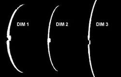
Prior to installing the Fortec GO, Templet used video cameras and remote monitors to allow operators to visually inspect the tube-forming process before welding. However, automating the process proved tricky because of the proximity to the TIG welder. “The TIG welder emits a broad-frequency spectra at high intensity,” explains Feiste. Using the Knotenpunkt laser line generator, which is adapted with discrete light filter lenses, the laser light reflected from the tubes service is stronger than the nearby welding emissions, allowing the Bayer filters running on the VRMagic camera to quickly and easily isolate the laser line in the image and convert the gray-scale image into a binary image (see Fig. 5).
The binary image is then fed via USB to the panel PC, which runs Knotenpunkt’s triangulation software underneath Fortec GO’s API. The triangulation routines analyze the line’s shape to determine the displacement of the laser line from the norm in x-y space and with the Fortec sensor-to-laser calibration data determines the z, or height, information for up to 480 points along the 40-mm laser line.
In addition to the accessibility of the software library for triangulation, Fortec chose Knotenpunkt laser line generator for its uniformity, which directly impacts the accuracy of the contactless distance measurement. “The laser line generators use a special optical lens to produce a line with no Gaussian profile—a line that is constant across the 40-mm stripe. When combined with the VRMagic camera, we are able to make 480-point measurements along the 40-mm laser line as it scans over the multilayer tubing,” explains Feiste.
null
The final 3-D profile is displayed on the panel PC, which also displays alarms should the diameter, spacing between inliner and aluminum tape, gap, or gap position fall outside of Templet set specifications (see Fig. 6). Currently, the Fortec GO system alerts line operators when tube-forming specifications fall outside of prescribed limits; however, Feiste says the company plans to further integrate the system with the TIG welder to control electrode placement and welding head position to increase the MLCP tube yield.
null
