Upon Closer Inspection
Turbine airfoils can be deburred and inspected in a robotic workcell that teams a smart camera with innovative LED lighting
To correctly mount airfoils to a turbine rotor shaft, the base of the airfoil must be precisely machined and finished. It is essential that machining the base of each airfoil’s mounting dove tail is done very carefully. After each airfoil is cut using a formed-end mill cutter, the base of each part must be deburred and inspected to ensure the correct tolerances have been met.
In the past, this process was performed manually by operators using deburring tools such as rotary wire brushes to finish each part. The operator would then manually inspect the airfoil to ensure each part conformed to the correct tolerance.
Automated process
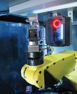
To automate this deburring and inspection process, AV&R (Averna Vision & Robotics) has designed a system that combines a robot and vision system (see Fig. 1). Originally developed for a large OEM aircraft-engine manufacturer in the northeastern USA, the system allows the operator to insert the airfoil into an entry fixture mounted in a single workcell. Once inserted, the system is initialized and a robot picks the part from the fixture and moves it to a deburring station where the base of each airfoil is deburred.
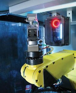
The robot presents a number of views of the part to a smart-camera-based vision system for inspection. After inspection, properly deburred parts are placed in an output cell, where they are moved to the next stage of production (see Fig. 2). Should any part fail the deburring or inspection process, it is rejected.
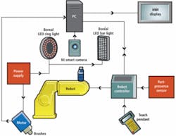
“In the design phase of the system,” says Michael Muldoon, business solutions engineer at AV&R, “it was important to tightly integrate the components of both the robot and vision system.” As each part is placed into the fixture, a proximity sensor interfaced to a PC running Windows alerts the operator that the part is in position.
“Developing the human-machine interface (HMI) in LabView,” says Muldoon, “allows the operator to visualize the status of the system, the part under inspection, and the statistics of each part as it is processed. When the part is detected the cycle starts automatically. An LR-Mate 200iC robot from Fanuc Robotics America is programmed with the coordinates of the parts location and where it is to be moved for the deburring and vision inspection process. Since this is preprogrammed,” says Muldoon, “the operator need only be aware of how to start and stop the deburring and inspection process.”
After the robot picks the part from the workcell it is moved to the deburring station. Here two rotary brushes are used to remove any burr that may have occurred during manufacturing and then to create a radius on the dove tail and platform edges. “After the deburring process,” says Muldoon, “the robot is instructed to present the part in a number of different views to a NI 1722 smart camera from National Instruments (NI).”
The advantage of using a smart camera is that it allows the customization of the hardware configuration to the customers needs. In a simpler system configuration where there is no HMI other than the teach pendent, the smart camera can run autonomously without sacrificing any of the algorithms and processing power of NI LabView. With the industrial communications protocols built into the camera, it can talk directly with most controllers and PLCs without the need for an intermediate PC.
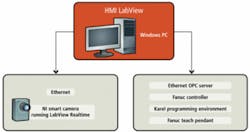
For the PC to interpret the position of the part, robot-coordinate and servomotor controller data were transferred to the PC using an OPC Server (OLE for Process Control), a software application that acts as a protocol converter to interpret software data from the Fanuc robot HMI and translate them into data that can be read as part of a LabView program (see Fig. 3).
Proper illumination
“Lighting plays a crucial role in detecting whether each part has been finished correctly,” says Muldoon. As each part is presented to the smart camera, its serial number must be read. Rather than use the embedded light source within the NI 1722, the part is illuminated with a red LED ringlight from Boréal Vision mounted to the front of the smart camera. Once the part is correctly positioned within 6 in. of the camera, this brightfield illuminator provides uniform illumination of the sample and an image of the part is captured by the camera.
Using LabView in real time in this application, explains Muldoon, Averna was able to embed National Instruments’ optical-character-recognition software (OCR) into the camera to perform the inspection. After the camera captures an image of the part, OCR is performed and the results are transferred to the host PC over the camera’s Ethernet interface. Should the system be unable to read the part, the system then prompts the operator to enter the OCR code manually.
If the operator cannot read the OCR code on the part, then he/she can manually reject the part using the LabView-based HMI running on the PC. If the part can be read automatically or if the code is entered by the operator, then several images of the part are again presented to the vision system for image analysis.
“To properly detect the surface features,” says Muldoon, “it was necessary to illuminate the part with darkfield illumination. Darkfield illumination provides highly contrasted images that detail scratches, surface defects, and the edges of each part.” This darkfield illumination was provided by placing blue LED bar lights from Boréal Vision at the side of the smart camera. As the part is rotated by the robot under this light, multiple images of the mounting grooves of the airfoil are captured.
Surface inspection
To perform the surface inspection of each part, the images are binarized and then filtered to highlight any surface defects. “In this way,” says Muldoon, “defects such as scratches, pits, and nicks can be properly classified.” Data regarding these defects were then compared with a known threshold limit that was preset by the programmer. These algorithms were embedded within the LabView program and also run autonomously within the smart camera. Should an airfoil fail this inspection, then the part is also rejected by the system and the reason for the parts failure displayed on the HMI. Should a part fail, it is then rejected and passed to a human operator who determines whether the part can be reworked or must be rejected.
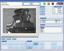
“Of course,” says Muldoon, “in the process of deburring the wire brushes will wear, and the status of these brushes also needs to be monitored.” AV&R used a closed-loop feedback structure to monitor the life of the brushes and automatically compensate for the wear and change in brush diameter. For preventative maintenance the system will also alert the operator when it is time to change the brush to ensure a stable and good-quality finish. To provide the operator with the status of each deburring and inspection operation; AV&R developed an HMI in LabView (see Fig. 4).
On this HMI, the operator is presented with a view of each part as it is presented to the vision system, a pass/fail counter that highlights the number and status of the parts processed, and the results of each inspection process. Thus, tasks such as serial number inspection and the results of surface inspection for different part positions can be visualized in one HMI system.
These systems cost from $150,000 to $500,000, depending on the complexity and size of the part to be deburred and inspected. AV&R currently has multiple systems installed in different jet-engine production facilities. “More important,” says Muldoon, “because the system is programmable, it can be easily adapted to deburr and inspect other parts such as tooling fixtures, automotive components, and metal housings.”
null
