Applying Algorithms

Most machine-vision problems can be solved with a commonly used set of image-processing algorithms
Ganesh Devaraj, Ajay Varma, and Ezhil Selvi K.
During the past few years, programmable smart cameras have become increasingly popular for handling inspection and error-proofing tasks in factories. The popularity of this product lies in the fact that it is compact, rugged, low cost, and easy to deploy. The ease of deployment arises not only because smart cameras are compact and fully integrated vision systems on their own, but also because they are programmable through a much simpler process than the traditional PC-based vision systems.

Vision experts prefer PC-based vision systems because of their open architecture, versatility, and high-performance computing capabilities, but developing and deploying one requires knowledge of a programming language and experience in image processing. Smart cameras, on the other hand, have a programming interface that hides much of the programming complexity from the user and, because of the highly interactive and learn-as-you-go nature of the programming process, demands significantly less prior experience in image processing.
The programming process for a smart camera consists of building a script, which is a sequence of image-processing steps. The most often tried step is pattern matching, in which a pattern (in the form of an image) is stored (learned) and the program searches for this pattern in subsequent images and when it finds a match, it returns a score that quantifies the extent of the match. For example, the image of a “good” part is stored as a pattern; during the inspection, good parts are expected to result in high pattern-matching scores and defective parts should produce low scores. Once a threshold score is set as the acceptance criterion the programming is complete.
While programming a smart camera using pattern matching is simple in principle, the pattern matching score can vary quite significantly—for example, due to changes in the way light reflects off the surface variations from one part to the next, or due to a host of other situation-specific reasons (some of which are described in the examples that follow). When pattern matching does not provide a reliable solution for a given set of imaging and part-handling conditions, a system integrator could invest in more hardware (lighting, optical filters, part fixturing, etc.) to bring more uniformity in the images.
Alternatives to pattern matching
As an alternative, it is worthwhile to try building a script (programming) using basic image-processing steps to address the problem before making new investments in hardware. An advantage of developing a script from low-level algorithms is especially evident when the algorithm fails for certain cases. One can step through the script and see where it fails and understand what needs to be done to solve the problem. This is unlike when one uses pattern matching, since the algorithm is essentially a black box. The simplicity of setting up the system is offset by its opacity when the algorithm fails.
One would imagine that the complexity of the programming would grow significantly when we go beyond pattern matching because of the large number of image-processing algorithms that one would need to learn in order to solve a problem. We studied this question using a sample set of 35 applications that were addressed using our smart camera without pattern matching.
This analysis is based on data collected from installations at our customer sites. The smart camera used in all these applications is Soliton’s Spot-It, which has a 640 × 480-pixel image sensor (color or monochrome) and a DSP for image processing. The programming was done using the Soliton Vision Artist, which is our programming interface to build the image-processing script.
Consider the following application where our customer, a major Indian auto component manufacturer, wanted to inspect a subassembly of a fuel injection system for the presence and proper placement of a rubber O-ring before integration into a larger assembly. The white post in the center is not always perpendicular to the imaging plane and this created enough variations that pattern matching did not give sufficiently discriminating scores between the good and defective parts (see Fig. 1). The integrator decided that pattern matching was not reliable enough for his setup.
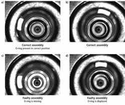
The integrators addressed this application by developing an appropriate image-processing script using Soliton’s smart camera D-Spot-It and LEDer1000 LED lighting. After some quick experimentation, they were able to handle all the cases correctly using just two image-processing steps. There is sufficient contrast to perform “threshold” on the dark O-ring in the center and the large outer dark ring; and to perform “fit circle” twice (with appropriate initial conditions for the edge-finding scan) to identify the center and radius of the O-ring and the dark outer ring, and to verify that the offset between the centers is within limits to decide on pass/fail.
A few validation steps such as verifying that the radii are as expected were included to ensure that the right objects were found through the fit circle steps. We have highlighted a few more applications that could not be solved easily using pattern matching, but were addressed by building simple scripts using our smart camera (see “Applications benefit from smart camera’s simple scripts,” page 20).
Analysis
A total of 18 image-processing algorithms were used to address the 35 applications that we studied. Figure 2 shows the number of applications in which of these algorithms were used (each algorithm is counted only once per application even if it is called multiple times within a script). The distribution fits a logarithmic curve reasonably well.
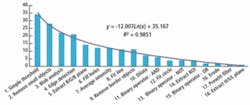
If we separate these algorithms into image analysis and image preprocessing types, only five of these 18 algorithms fall in the image-analysis category: 1) blob analysis, 2) edge detection, 3) average intensity, 4) fit straight line, and 5) fit circle. It is interesting to note that all 35 applications were solved using just five image-analysis algorithms.
All but one of the applications used a simple threshold to obtain a binary image, immediately followed by remove small objects to remove noise specks. The most often used image-analysis algorithm turns out to be blob analysis, which identifies all of the connected particles in the image and filters based on the criteria specified by the user (such as area) to isolate the particle(s) of interest. The second most frequently used image-analysis algorithm is edge detection, which finds edges along a specified straight line.
Conclusion
Pattern matching is an extremely useful image-processing tool for machine-vision applications, and it is especially indispensable in applications such as robotic pick and place. However, it is not the right tool in many applications. Our analysis shows that a majority of smart camera applications can be solved using only a small number of image-processing algorithms that can be learned quickly and used very effectively.
We have counted as many as 120 separate image-processing algorithms in libraries from different established vendors, but most of these are used very rarely if at all, except by experts. This has the unmistakable characteristics of a “long tail” phenomenon: Vendors include them in their libraries because it costs essentially nothing to carry them in the list, and it may be of interest/use to a few users.
We concede that there is certain to be a bias in the choice and usage of these algorithms based on the training and orientation given to our integrators and customers, but what is important to note is that all of these applications were solved successfully using these few algorithms.
Ganesh Devaraj is CEO, Ajay Varma is architect–product marketing, and Ezhil Selvi K. is applications engineer, Soliton Technologies, Bangalore, India; www.solitontechcom.
Applications benefit from smart camera’s simple scripts
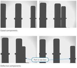
Fuel filter port height inspection
Inspection requirements
To identify defective components where the three ports on the filter are not of the same and correct height.
Complicating factors
The algorithm has to compensate for the rotation of the base and the associated changes in pose.
null
Logic
A thresholding operation, followed by blob analysis, results in two to three blobs, depending on the orientation of the component. By detecting edges on both sides of these blobs, four to six points are detected that correspond to the edge of the step present at the middle of each port. The positions of these edges can then be compared to determine if the step height and, consequentially, port heights are correct.
Algorithms used
Simple threshold, blob analysis, edge detection
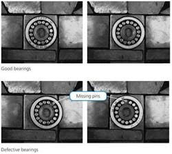
Roller pins in bearing inspection
Inspection requirements
To identify defective bearings where improper manual assembly or subsequent handling has resulted in the dislodging (absence) of one or more pins.
Complicating factors
Presence of grease around bearing pins.
Non-uniform light reflection due to surface irregularities on the ends of individual pins.
null
Logic
Thresholding and blob analysis identifies the high-intensity regions of the image. By filtering based on area and location, the bearing pins are isolated and can be counted.
Algorithms used
Thresholding, blob analysis
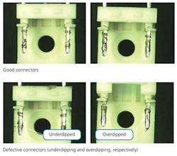
Solder coverage on connector
Inspection requirements
To identify defective connectors where the two leads (pins) have not been dipped in solder correctly (i.e., up to but not exceeding the middle of the pin).
Complicating factors
The pattern of copper wire winding on the pin is not uniform. There is very little contrast between copper wire and the solder-covered area.
null
Logic
Extraction of the saturation plane followed by thresholding isolated the uncovered copper wire from the background. Average intensity then indicated how much of the wire was covered by the solder.
Algorithms used
Saturation plane extraction, thresholding, average intensity
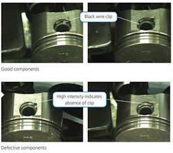
Piston wire-clip inspection
Inspection requirements
To identify defective piston assemblies in which a black wire-clip has not been assembled. The pistons are on a conveyor.
Complicating factors
Very minor difference between good and defective assemblies.
null
Logic
By removing border objects after thresholding, the hole in the piston can be identified. Using this as a reference, the step where the clip is to be present is found and the average intensity in that region is calculated. The intensity is low if the clip is present, while it reflects significant light if the clip is absent.
Algorithms used
Threshold, blob analysis and filter, remove small objects, remove border objects, fill holes, average intensity
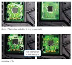
PCB glue inspection
Inspection requirements
To identify defective PCBs in which glue is present over the central IC.
Complicating factors
Large variation exists in glue appearance before and after drying. Variations appear in the characters on the IC and its color. Uneven surface of glue results in white patches due to irregular reflection.
null
Logic
The image is thresholded to extract only high-intensity pixels. The average intensity of the pixels over the IC is found. Small quantities of glue increase the average intensity value while the presence of a very thin film of glue on the gray IC makes it appear black. Edge detection is used to locate the IC.
Algorithms used:
Threshold, blob analysis and filter, edge detection, dilate, average intensity