Multifunction test targets are used to test and calibrate imaging systems
Nello Zuech, Vision Systems International
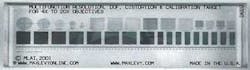
In the past, verifying the performance of an imaging system required using a number of calibration targets. Today performance evaluation and calibration of an imaging system has become easier with multifunction targets such as those offered by Max Levy Autograph (Philadelphia, PA, USA; www.maxlevy.com). These targets contains several patterns, which in combination perform the function of several individual targets, including standard resolution targets, distortion targets, depth-of-field (DOF) targets, and linear calibration measurement scales (see Fig. 1).

Each target is patterned in double-layer, reflective evaporative-deposited chrome that allows the targets to be used in top-lit, through-the-lens, and bottom-lit configurations. Each target is patterned on quartz glass optimized for flatness and parallelism. To accommodate various magnifications and fields of view (FOVs), each feature on the target is reproduced in multiple scale configurations. These include variations in frequency, overall pattern size, spacing, and linewidth. This makes such targets useful in a range of optical configurations and camera interfaces.
Two versions of each target are offered. The first version is intended for low- to mid-range magnification optics and optical systems such as stereo-optic microscopes, machine-vision systems, video microscopy systems, linescan cameras, macro lenses, and telecentric lenses. The second version is designed for mid- to high-power magnification systems.
Patterns associated with each target include a series of concentric circles that are used to assess the FOV and measure imaging system aberrations such as astigmatism and spherical aberration. Square grids with intersecting straight lines spaced at regular intervals orthogonal to each other with different spacing and linewidths can be used to evaluate different magnification factors and FOVs. These are also useful for detecting pin-cushion and barrel distortion. For machine-vision systems, such grids can be used to test the accuracy of sub-pixel software routines by comparing experimental results to the known specifications of the grid.
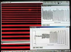
To determine the modulation transfer function (MTF) of a system, patterns of evenly spaced alternating clear and opaque lines known as Ronchi rulings are used. These are defined in terms of frequency either in line pairs per millimeter (lp/mm), or line pairs per inch (lpi). By viewing progressively higher-frequency rulings, the user can determine the point at which the system can no longer resolve detail (see Fig. 2). The rulings can also be used to measure fine linewidths and spaces. Using the Ronchi rulings allows the user to evaluate resolution over the entire FOV and DOF of the lens/camera system (see Fig. 3).

To check the FOV of magnifiers, microscopes, and machine-vision systems, a precision linear micro-scale graduated with a repetitive line pattern, with varying length lines, can be used. Additionally, the linear micro-scale can be used as a reference standard for calibrating digital motion stages and non-contact metrology systems.
Precision edge blocks are provided with each of the two versions of the multifunction target. The purpose of edge blocks is to raise one edge of the target to a known height so that the target is at a specific angle. Edge blocks are specifically designed for the magnification range of the lens system placed under test. For example, low-magnification systems typically have both a larger FOV and a greater DOF than high-magnification systems. High-magnification systems also have a shorter working distance, which limits the angle to which the target can be raised. Used in conjunction with Ronchi rulings and/or linear micro-scales, edge blocks provide a DOF measurement for the optical system. By measuring the “in-focus” length along the surface of the target, the DOF can be calculated.
Nello Zuech is president of Vision Systems International, Yardley, PA, USA; www.imagelabs.com/vsi.p
Understanding imaging specifications
Two of the most important qualities of any image are contrast and resolution. Image contrast specifies the range between light and dark portions of an image and is normally measured between the relevant features in the image and the background surrounding those features. The ideal image has ultimate contrast, with the desired information having intensity values of absolute white and background intensity values of absolute black.
Spatial resolution—the ability to resolve two closely spaced objects—is a distance measurement associated with the smallest detectable object. The resolution required depends on the task of the imaging system. For example, if a system is needed to locate a part to within one inch, the system resolution needs to be less than one inch.
To capture an image requires both optics and an image sensor mounted in a camera. Except for the scaling or magnification factor, in an ideal optical system, the image should be as close to a faithful reproduction of the 2-D projection of the object. Consequently, attention must be paid to any distortion that could be introduced by the optics. Not only are the properties of the lens important but also those of the image sensor (number and size of pixels and dynamic range) and the mounting of the image sensor in the camera. Any mis-registration, tilt, or skew will affect performance. Both sensor properties and incorrect mounting can impact system performance.
Two of the most critical parameters of an imaging system are MTF and distortion. MTF can be described as the spatial frequency response, which combines the effects of sensor resolution, focus accuracy, lens quality, and contrast. Geometric distortions reduce the geometric fidelity of the image and result in the magnification varying with distance from the optical axis of the lens.
Two common types of distortion are pin-cushion and barrel distortion. These distortions are observed as changes in magnification along the lens axes. With pin-cushion distortion, magnification increases as the distance from the center increases. Barrel distortion has the effect of decreasing magnification away from the image center. Lens distortion is especially relevant in machine-vision systems used in gauging applications. Another critical parameter in an imaging system is DOF, the portion of a scene that appears sharp in the image.