Winn Hardin, Contributing Editor
Portable hematology machines offer doctors in offices as well as remote locations in developing nations a chance to quickly scan for some of the world’s most fearsome diseases such as malaria. These hematology systems include optical testing and centrifuge systems to scan disposable glass tubes holding special reagents that react with tainted blood samples. The systems are essentially plug and play, requiring no special technical knowledge, which makes them uniquely attractive for both the family doctor’s office as well as frontier clinics.
Recently, a maker of portable hematology scanning systems contracted Aptúra Machine Vision Solutions to retrofit existing reagent-tube manufacturing equipment to inspect for the presence and location of lightly contrasting liquid reagent sprayed on the inside of 3-in. glass tubes. Challenges for the system included imaging the sprayed liquid on the inside of a curved glass tube with sufficient accuracy to locate and measure voids in the reagent coating as well as verify that the coating is present to within a certain distance of each end of the tube.
Finally, the solution needed to complement existing manufacturing equipment. This posed a unique challenge in illumination, optics, and image processing when engineers determined that a backlit machine-vision system would provide the best contrast for the inspection task.
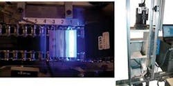
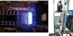
Aptúra chose a complementary LED light source along with special material to both diffuse and reflect the light. Consequently, the tubes are illuminated from above for the PPT Vision Impact smart camera vision system as they traveled down a chain drive at burst rates of up to five tubes per second (see Fig. 1).
Tube lineup
The blood-filled tubes are loaded into the automated tester and, as long as the right amount of reagent is in the tube, will provide the same accuracy as laboratory-conducted blood tests. The manufacturer produces a number of different tubes, each with its own reagent and position requirements for the reagent.
Several conditions complicated the design and installation of the machine-vision inspection system. First, the tubes are small and curved, requiring a camera of relatively high spatial resolution with some unique image-processing capabilities to separate a translucent inner coating from the clear glass tube.
The tubes do not stop for inspection while traveling at burst speeds of up to 300 per minute, meaning that either the camera would need a fast shutter or a strobe light source would be required. At the same time, the chain drive conveyor precluded Aptúra’s president and chief engineer, David Dechow, from placing the illumination system behind the tube to enhance the contrast of the translucent reagent. In addition, because the vision system needed to be able to image voids in the reagent coating as small as 0.5 mm across a relatively wide area—each tube measures about 3 in. long—the camera and optics would need to be carefully chosen to limit spatial distortion while maintaining speed and spatial resolution.
Blood orange
“Coverage of the reagent inside the tube is critical to this application,” explains Aptúra’s Dechow. “You can’t have too much or too little or have it in the wrong place. Parts of the tube also needed to be without reagent and clear. A backlight would have been optimal for this application, but because of the architecture, we couldn’t use that.”
The speed of the moving tubes also meant that a strobe light might be the best solution. At the same time, the system would need as much light as possible from each flash because the designer determined that a long-focal-length lens on a camera placed a few feet away would allow the vision system to image the entire length of the tube without introducing too much distortion, making the void area calculations more difficult to perform.
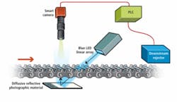
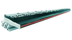
Since the reagent had a slight orange tint, Dechow decided a complementary color light source at the opposite end of the visible spectrum would work best. He chose a linear blue LED array from CCS America to illuminate the tubes from the front and placed a common white photographic material behind the tubes at the inspection point (see Fig. 2).
By adding a half-barrel line lens to the LED array, Aptúra’s design focused the light into a relatively thin line that reflected off the diffusive/reflective photographic material and effectively backlit the tube under inspection. To increase the amount of light per flash, Dechow overdrives the LEDs with a Gardasoft Vision LED driver and power supply.
Blood test
A PPT Vision Impact smart camera system collects the images and processes the results. The need for a compact camera head with high resolution relative to the field of view required the use of a 9200 Series C camera connected to the Impact smart camera controller, processing elements, and network hub. To reduce optical distortion, Dechow mounted an Edmund Optics axis double-Gauss lens with low modulation transfer function (MTF) to maintain image integrity to the camera.
“There are other lenses out there, but this is a good one for creating high-line-accuracy images,” explains Dechow. “We were also able to partially scan the CCD camera to just a hundred rows or so because we were imaging a long, narrow part. You’d need a CMOS camera for vertical and horizontal partial scans, but most CCDs can do vertical partial scanning.”
Partial scanning helped to reduce the image-processing requirements for the vision system, which was helpful because the low-contrast images challenged Aptúra to come up with some unique approaches to inspecting the reagent inside the glass tube.
“If you look at a glass tube, the middle is clear and the sides are dark from the curve of the glass,” says Dechow. “We used some linear morphology functions to smooth the image and improve the contrast between reagent-covered glass and ‘clean’ glass. We had to be careful that we didn’t smooth out the voids, of course, or overlook areas of light contrast where the reagent might only cover one side of the tube.”
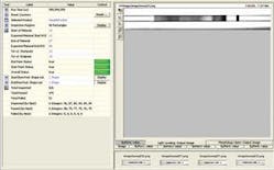
The system needed to be able to identify, measure, and locate voids between 0.5 and 1 mm, depending on the type of blood test, as well as lightly covered areas (indicated by areas of orange tint that fall below a certain intensity threshold). The slight variations of insufficiently thick coatings meant that simple edge detection and blob analysis would be difficult to implement with sufficient confidence. Instead, Aptúra applied more than 100 masks over the image, each highlighting a single section of the tube (see Fig. 3).
If the values for that section fall below a certain point, the coating is determined to be insufficient. The Impact controller passes a fail signal to a shift register in a nearby PLC, which tracks the defective tube until it reaches a downstream rejector and is blown out of the chain drive.
According to Dechow, the process would benefit from additional inspection of the glass tube to detect chips, cracks, or other defects. This would, however, require additional cameras or the implementation of an inspection system at another point in the process where more of the tube is visible.
features, advantages, benefits
In designing the lighting for the reagent glass tube inspection system, David Dechow, president of Aptúra Machine Vision Solutions, increased the amount of light per flash by overdriving the LEDs.
“It’s our belief that LEDs should be overdriven and flashed in most applications to extend the life of the LEDs, which is one of their main advantages over other illuminators,” explains Dechow. “At constant currents, LEDs have to be operated in the milliamp range, but if your duty cycle is low enough, meaning there’s enough time between flashes, you can drive them up to between 7 to 12 amps without damaging the LEDs. By shortening the strobe duration and overdriving the LEDs, we’re able to get more photons out of the light and on the target and stop the motion of the tube as it passes in front of the camera while extending the life of the system.”
Company Info
Aptúra Machine
Vision Solutions
Lansing, MI, USA
www.aptura.com
CCS America, Burlington, MA, USA
www.ccsamerica.com
Edmund Optics, Barrington, NJ, USA
www.edmundoptics.com
Gardasoft Vision Limited
Cambridge, UK
www.gardasoft.com
PPT Vision
Bloomington, MN, USA
www.pptvision.com
