Baking the Drum
Winn Hardin, Contributing Editor
For heavy equipment such as tractors and bulldozers, the ability to stop momentum is more important than acceleration. Braking systems for such equipment are critical and each component must be tracked for product liability or potential recall. An infrared (IR) system has been developed by system integrator TEC Automation to perform this function during the brake drum casting process.
Most heavy equipment uses drum brakes rather than disc brakes. Each drum is formed by heating a steel shell that is made by bending steel strips of varying widths—depending on brake type and vehicle—into a circle. The shell is placed into a centrifugal casting machine and heated to a bonding temperature of approximately 1800°F.
Molten iron at approximately 2700°F is then poured into the shell as it spins at high speeds. The spinning shell forms the molten iron in a homogenous layer that bonds to the steel shell and can then be machined to a specific thickness to create the final brake drum.
A global manufacturer of braking systems for heavy equipment recently contracted TEC Automation to replace several older laser pyrometers with an IR camera system to monitor casting process parameters. TEC Automation was able to provide the manufacturer with a comprehensive control and data acquisition system, as well as part imaging and measurement specific to each drum instead of one-size-fits-all spot measurements as in the past.
This flexibility and customization has eliminated the need for operators to adjust camera placement and calibration for each model change and has given supervisors the ability to monitor and control temperature settings across the network. The resulting process control has eliminated almost all measurement inconsistencies due to human error and is resulting in more consistent product quality, regardless of shift or operator.
Covering all the parts
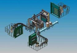
The system design is based on a fixed A320G infrared camera from FLIR Systems with a field of view capable of covering all part numbers. By using OLE commands with Microsoft Excel, data are captured by the camera and then stored on the network. Each part is subsequently marked with a laser-engraved Julian date and serial number that corresponds to the data log (see Fig. 1).
If there is a failure of a component in the field, the data for that specific brake can be retrieved and analyzed to determine whether there were flaws or inconsistencies in the process when the part was poured. Other parts made during that same time can also be reviewed for the possibility of other impending part failures.
Temperature is critical in centrifugal casting operations. If the temperature of either the steel shell or the molten filler material is too high or low, the two materials will not properly bond at the molecular level. As with a “cold joint” in welding, the resulting seam is not homogeneous and can result in fragile and brittle assemblies that could shatter during operation.
“We take three pictures of the centrifugal casting process: one of the heated shell, another just after the pour, and a third picture just before it exits the station,” says Rob Greene, senior account manager at TEC Automation. “Everything started with the customer’s need for consistency.
“After observing the production,” he says, “it became apparent that personnel on different shifts had different preferences for how they set up their process. The impact of this on part quality was that it was entirely probable that parts made on three different shifts had three different sets of production parameters. This is not to say that one shift made good parts and the other two shifts made scrap. I am stating that often each shift made different parts.”
What the customer really needed was a system that eliminated this human preference variable. Greene adds, “They needed a closed-loop system and that is what we delivered. At first, they could not qualify why the parts were inconsistent, as they weren’t collecting production data. We knew we needed to implement a data acquisition system first. The infrared camera was perfect for collecting the temperature data. First we gathered the data; then we closed the loops.”
The drum brake production line actually produces 30 different types of drums, each varying in diameter and width of the steel shell, and therefore the brake drum. The manufacturer determines the perfect temperature for the shell and molten iron for each model, as well as the time required to spin the casting before it is ready to be removed and sent to machining.
Turning the brake
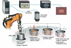
The drum brakes are cast on a large index table built to accommodate the various steps in production. To start the operation, a robot loads a steel shell into the first station. The shell is induction heated to 1800°F, and the table indexes to the pouring/inspection station. An older-model Allen-Bradley PLC-5 controls the index table. After the shell is loaded and the table indexes to the pouring station, the PLC-5 sends an acquisition signal to a new Allen-Bradley ControlLogix PLC that acts as the bridge between the vision system PC and the PLC-5 (see Fig. 2).
“We could have replaced the PLC-5 with the ControlLogix PLC, but the existing PLC was running several proprietary scripts that controlled the heating elements, fans, etc.,” explains TEC Automation electrical engineer Ryan Hutcheson. “The ControlLogix PLC is a relatively new model that will be supported for many years to come. When the customer is ready to expand the system, the new PLC will be ready to run the show.”
The PLC-5 sends a trigger signal to the vision system via the ControlLogix PLC along with the part and model number. Assuming the part passes the three inspection steps, the temperature results for each of the three steps will be recorded in a Microsoft Excel spreadsheet that is saved locally as well as on the plant network. An infrared image of the part is likewise saved to protect the manufacturer from future liabilities. If the part passes the inspection process, the vision system will send the date, part, and model numbers to an Electrox fiber laser part-marking system, which engraves the number on the outer shell of the brake drum.
A thousand points of data
Each image from the A320G camera feeds across a GigE cable to the host PC, which runs FLIR’s Thermacam Researcher software and the Excel spreadsheet with necessary scripts. The Thermacam software converts the image data to actual temperature values, which are stored as comma separated values (CSVs) in the spreadsheet.
The software also allows designers to create multiple measurement windows and then mask parts of the image that are not part of the analysis (see Fig. 3). After the part is inspected, the index table cycles again, the part is marked, and then indexes a final time for robotic unloading of the table.
“We run the camera constantly while the casting is occurring, so we generate thousands of temperature values,” says Hutcheson. “We save all these data points and create a part-specific concatenated file that contains all temperature as well as other process information in a searchable format. As this file can quickly become ‘sensory overload’ due to its sheer size and volume, we also create a second file in which we save only the peak high, low, and average temperatures along with three images for each part.”
He adds, “If needed, the customer can quickly reference this condensed data to check or graph a batch or range of parts to check that the temperatures were right for the steel shells to properly bond with the molten material. If there’s a question years down the road about the quality of a specific drum, then the customer has not only the average data and reports but also the complete part file and process data specific to that part and can go back to the images and collect the temperature values to prove that the part was manufactured to spec.”
Hutcheson said he chose the A320G because it is a high-resolution IR camera that calibrates internally to a black body between each part. While IR image files are typically smaller than visible images because the sensor arrays are smaller than an average industrial CCD or CMOS imager, Hutcheson said it was important to use Gigabit Ethernet because the customer may expand the system in the future to include multiple cameras.
“Right now, we’re only using about 10% of the bandwidth, but if they add five more cameras, it won’t take long before we’re glad we have the extra capacity,” explains Hutcheson. “The ControlLogix PLC is capable of managing much more than its current bridge-and-traffic cop duties.
“In the future,” he concludes, “the customer intends to expand this system to monitor and control more post-pour processes. As they start adding more functionality and closing more loops in the manufacturing process, they’ll be glad they have the extra horsepower we built into the system.”
Company Info
Allen-Bradley, Milwaukee, WI, USA
www.ab.com
Electrox, Indianapolis, IN, USA
www.electrox.com
FLIR Systems, N. Billerica, MA, USA
www.flir.com
TEC Automation, Canton, GA, USA
www.tec-automation.com


