Engine of Flight
C.G. Masi, Contributing Editor
When Lockheed Martin won a contract to upgrade engines on the US Air Force’s C-5 Galaxy fleet, they called on special-equipment supplier Delta Sigma Corp. to develop a vision/boring tool (VBT) to ensure correct alignment of the new engines. As Ken Myers, Lockheed Martin’s mechanical engineer in charge of the engine pylon replacement, notes, “There are a lot of complications when you are working with very large components that must be very accurately positioned. The new vision and servo alignment system will reduce risk, reduce job hours, and improve the precision of our alignments.”
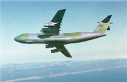
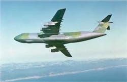
The four engines on a C-5 are mounted to the underside of the wings, beneath the aerodynamically shaped pylon skins (see Fig. 1). The engines attach to a wing at three mounting points: two at the wing’s leading edge (designated A and B), and the third farther aft (designated C). Because the new engines provide 22% greater thrust, stronger engine-mount fittings must be installed.
The VBT sets proper alignment for the engine fittings. The fittings are held against the bottom wing skin by a large number of fasteners installed through holes in the fitting and the wing. When the engine is installed, a shim is used to set its pitch alignment relative to the wing.
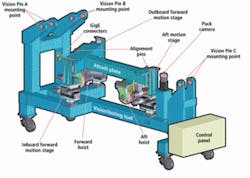
The process starts with technicians fastening an attach plate to the wing through existing holes in the fitting. Pins on the attach plate fit into holes in the VBT to ensure repeatable alignment. Initially, the VBT is aligned to the A, B, and C mounting-pin holes to within 0.010 in. (see Fig. 2).
To pick up the existing hole pattern, technicians clamp the new fittings to the wing, then backdrill four of the existing fastener holes to transfer the hole pattern to the new fittings’ mating surfaces. The VBT then has to come down to make way for removing the new fittings so the rest of the mounting holes can be drilled out on numerically controlled equipment in the machine shop.
Alignment process
The VBT alignment process relies on “vision pins,” which Delta Sigma developed for aligning wing-mounting fittings at Lockheed Martin’s F-22 Raptor manufacturing facility (see “Vision-guided system speeds F/A-22 assembly,” Vision Systems Design, September 2004). The vision pins are inserted into the A-, B-, and C-fitting holes to check the alignment of the VBT structure with the engine-mount fittings.
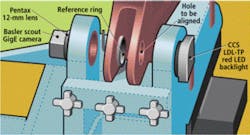
Vision pins for the C-5 project consist of three components: a Basler scout GigE area-scan monochrome camera with 1624 × 1234-pixel resolution and a short-focus Pentax C61215TH 12-mm (fisheye) lens; a custom-machined reference ring; and a CCS model LDL-TP 51 × 51 red LED backlight. The reference ring fits into the camera-side portion of the A, B, and C clevis, while the camera observes the edges of the backlight side portion (see Fig. 3).
The centrally located white circle in the image captured by the camera is of the unobscured portion of the backlight. Outside that circle is a mottle annulus, which is the image of the inner surface of the fitting hole. The white circle’s outer circumference is actually the sharp corner where the fitting’s far side has been bored through to machine the hole (see Fig. 4).
Similarly, the outer circumference of the mottled annulus is the edge where the fitting’s near side meets the hole’s inner surface. A dark annulus image is the unlit near side of the fitting. Finally, a bright annulus represents the reference ring’s machined inner surface.
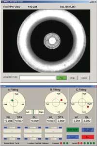
If the vision pin—and therefore the VBT—is perfectly aligned to the fitting, all the circles in Fig. 4 will be mutually concentric. The vision-pin software locates these circle centers and from their relative positions in the image calculates the magnitude and direction of any misalignment.
The software displays alignment errors for the A-, B-, and C-fittings. Three circles graphically show the degree and direction of misalignment between the vision pins and the fittings. Looking at the A-fitting display, the inner circle represents the 0.010-in. tolerance specification. The small colored circle represents the misalignment measurement. This small circle’s diameter represents the uncertainty (0.001-in.) in the vision pin’s measurement.
The colored circle lies entirely within the inner tolerance circle, which means the A-fitting alignment is within tolerance. The software confirms this by coloring the small circle green. The B- and C-fitting alignments, however, are not within tolerance so those circles appear red.
Aircraft designers use a station (STA), buttock line (BL), and water line (WL) coordinate system borrowed from naval architecture. STA represents the distance aft from the aircraft’s nose. BL refers to the distance port (left) or starboard (right) from the central symmetry plane. WL refers to the distance above the lowest part of the craft, which is the keel of a ship and (usually) the lowest part of an aircraft’s fuselage.
A modified version of the vision pin was designed to set the C-fitting’s WL axis alignment (see Fig. 5). Experiments showed that using the hole in the C-fitting for alignment did not work well. Instead, the Delta Sigma team devised an auxiliary C-Fitting Locator (CFL) to provide a proxy target for C-fitting alignment.
The CFL is a plastic part fabricated using the fused deposition modeling (FDM) process. The CFL has a flange drilled out with the same template as the C-fitting attachment holes. It carries a contrasting-color puck for a fourth vision pin to target.
This fourth vision pin works very similarly to the other three, but instead of looking through a backlit hole, it looks at the puck’s front surface lit by an LED ringlight attached to the camera. As with the other vision pins, the alignment goal is to achieve concentricity between the puck’s circumference circle and a reference ring installed in the camera housing. The camera views both the reference ring and puck face illuminated by the ringlight. Water line alignment is determined by comparing the ratio of the puck-image diameter to that of the reference ring.
Automated system
The goal of the VBT alignment process is to maneuver the VBT clevises—fabricated to match the mounting points of the new engine—into position around the holes in the old fittings. Four cameras, one each for the three vision pins and one for the puck alignment, provide images over Gigabit Ethernet to the host computer, which is a standard Dell laptop running Microsoft Vista Pro. Each camera links through one port of an Advantech EKI-2728 eight-port GigE hub. A fifth port connects to the host, leaving three ports for expansion.
The controller runs a vision-pin analysis algorithm written by Delta Sigma and the Cognex VisionPro image-analysis software environment. The VisionPro software acquires and analyzes images from the four cameras. The analysis algorithm determines offsets based on these results. The offsets then go to a Yaskawa MP2308-SIEC eight-axis motion controller, which drives Yaskawa 100-W servomotors through Yaskawa Sigma5 inverters to move the vision pins iteratively into alignment.
Each time, the control algorithm takes the measured offsets and multiplies them by a predetermined factor less than unity (to avoid overshooting by reducing the movement size) to find a new target location closer to the ideal position. It then sends servo movements needed to reach the new location. Repeating for the next iteration steps the vision pins closer to the ideal location until the measured offsets are within tolerance without overstepping. It usually takes no more than two to three iterations to get the VBT within tolerance.
The ability of the VBT to ensure correct alignment for the new engines is a great benefit to Lockheed Martin as it undertakes the C-5 upgrade contract. Automated measurements using the vision-pin technology give technicians confidence that they can step through the engine-upgrade procedure without errors.
features, advantages, benefits
Breaking with recent trends in advanced vision-system design, Delta Sigma chose to incorporate simple cameras rather than cameras that carry onboard intelligence. The cost and size advantages of these simpler cameras were more important than smart cameras’ speed and distributed processing advantages. “You could buy a smart camera that does everything we need to do,” states Brett Haisty, vice president of engineering at Delta Sigma, “or you could buy four simple cameras and one copy of the image-analysis software and it actually costs less.”
Haisty says that reducing the camera’s size by moving the image-analysis hardware back to the host computer turned out to be the most important consideration. “Very precise, highly reliable measurements are essential for our application. Using a standard high-resolution camera coupled with the processing power available in a modern PC yields sub-mil accuracies over an area of about two inches in a few milliseconds.”
Company Info
Advantech, Irvine, CA, USA
www.advantech.com
Airbus Industrie Schiphol
The Netherlands
www.airbus.com
Basler, Ahrensburg, Germany
www.baslerweb.com
Boeing, Chicago, IL, USA
www.boeing.com
CCS America, Burlington, MA, USA
www.ccsinfo.com
Cognex, Natick, MA, USA
www.cognex.com
Delta Sigma Corp.
Kennesaw, GA, USA;
www.deltasigmacorp.com
GE Aviation, Cincinnati, OH, USA
www.geae.com
Lockheed Martin
Bethesda, MD, USA
www.lockheedmartin.com
Neugart USA, Pittsburgh, PA, USA
www.neugartusa.com
Pentax
Golden, CO, USA
www.pentax.com
THK, Schaumburg, IL, USA
www.thk.com/us
Yaskawa Electric America
Waukegan, IL, USA
www.yaskawa.com
