Drum Roll
Winn Hardin, Contributing Editor
The quality of the surface of a laser printer drum is directly tied to the quality of the printed page. Therefore, it is critically important to have a very uniform drum surface; otherwise, field defects, field nonuniformities, or other artifacts will be transferred onto the printed page. Printer manufacturer Lexmark asked machine-vision specialist Boulder Imaging to create an automated quality inspection system that could do more than just “pass” or “fail” a drum based on the presence or absence of surface defects.
Each printer drum is essentially composed of three parts: the aluminum core, a charge generation layer, and finally a charge transport layer where the toner is released to the paper. “Part of the challenge of the system is to be aggressive at detecting flaws while characterizing these defects so that engineers can adjust the process,” explains Jie Zhu Kulbida, vice president of R&D at Boulder Imaging.
Each printer drum is essentially composed of three parts: the aluminum core, a charge generation layer, and finally a charge transport layer where the toner is released to the paper. “Part of the challenge of the system is to be aggressive at detecting flaws while characterizing these defects so that engineers can adjust the process,” explains Jie Zhu Kulbida, vice president of R&D at Boulder Imaging.
To accomplish this, Boulder Imaging developed a linescan-based system that both inspects the drums at rates of 80 parts/min and guides robots to sort the drums into “pass” and “fail” groups. The design team also built an operator workstation for each line that allows the engineer to view defect data as well as to perform rule-based classification of defects into likely causes on the production line, giving the engineer an accelerated view of how to improve quality.
High-res demands flexibility
The defects on a printer drum can be very small, as well as subtle. For this reason an extensive set of image-processing routines is required to adequately define and characterize defects.
Using a phased approach, Boulder Imaging installed three of its High-Performance Digital Video Recorder (HPDVR) lines, two on a 3000-part-per-hour line, and one on a 2000-part-per-hour line. “In both cases, by using an eight-core Xeon microprocessor in the PC, the bottleneck isn’t the image processing or machine vision, but the robots,” adds Kulbida.
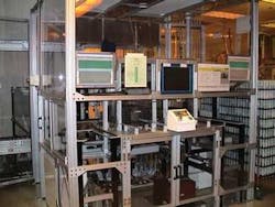
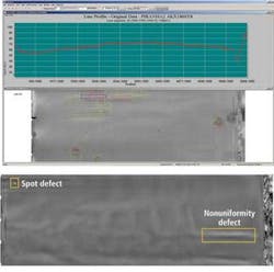
To inspect a drum in the work cell, the HPDVR system needed to be able to find spot defects, such as bubbles, inclusions, and scratches as small as 50 μm, and nonuniformities in the two coating layers that could be quite a bit larger but lack the defined area of a spot defect—at the same time the HPDVR identifies the region and layer for all defects found (see Fig. 1).
“Aluminum core pieces typically have high-contrast defects with very noticeable edge properties to them,” explains Boulder Imaging’s CEO Carlos Jorquera. “Defects in coating materials tend to be uniformity variations, as well as bubbles and streaks. Finally, there are handling defects, such as scratches on the drum coatings, which are typically caused by the robots loading or unloading the drums.
“Part of the challenge,” he continues, “was to aggressively find and characterize the different defects, and attribute them to the core or to different layers, not just so the engineer could adjust the production equipment, but so that the technician could determine whether a failed drum can be saved. For instance, a defect in coating can be removed and the drum recycled, but a defect to a core pretty much means ‘scrap the drum.’”
When the drums—which range from 20 to 40 cm in length and up to 3 cm in diameter—enter the HPDVR inspection station, the charge layer and transport layer have already been applied to the aluminum core. The drums arrive in numbered trays arranged into a 9 × 9 array.
A barcode reader upstream of the HPDVR station reads the information on the tray and sends that information to a nearby programmable logic controller (PLC), which queries the plant’s manufacturing database for the particular drum type. This information is passed via Ethernet to the HPDVR, which then selects the appropriate inspection recipe for that product.
The drum is flat
When the tray reaches the inspection station, a nearby photoeye triggers the first of two six-axis Adept Technology robots to unload the first row of nine drums, which it does in a single step using a specially configured end effector. The robot loads the nine drums onto one of three inspection sections. Prior to collecting the first image, the HPDVR system calibrates the camera to correct for nonuniformities between pixels as well as for spatial variability in the LED lighting.
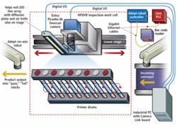
The inspection area consists of three spinner assembly sections side by side, each section accommodating nine drums that are spun in unison. The camera assembly is mounted on top of a long-travel (~9 m) linear stage from THK, allowing it to be precisely positioned in front of each one of the 27 possible drum locations (see Fig. 2).
While one section receives new drums ready for inspection, the second section is actually using the camera assembly for drum-by-drum inspection. Simultaneously, the third section is sorting drums into “pass” and “fail” trays ready to carry the product to the next step in the laser cartridge manufacturing process. Because the table is “manned” by two of the Adept robots, the workstation can load and unload drums while other drums are being inspected.
The camera assembly includes a DALSA 6k-pixel Piranha linescan camera with dual outputs, a custom mounting fixture that provides precise alignment for the camera’s rotation and tilt relative to a drum’s vertical axis, a Volpi red LED line light for illumination of the drum’s surface and layers, and an Exair air-knife to remove any potential particulates that may have landed on the drum after coating (see Fig. 3).
As the camera moves into position, the HPDVR system sends a 5-V signal through an I/O line built into the Camera Link capture board to the rotary table to rotate the first drum. A separate I/O line also sends trigger signals to the nearby LED driver to operate the light as a strobe in order to reduce heat and extend the life and stability of the light.
Light from the nearby red LED line light with a diffusion plate reflects off the drum surface and is captured by the perpendicular linescan camera. “These drums are highly reflective products, primarily via specular reflections,” says Boulder’s Jorquera. “For these reasons, and because they’re cylindrical, the angle of illumination to the drum needs to be very precise.”
Although they use various cameras from different manufacturers depending on the application, Boulder’s Jorquera chose the DALSA Piranha for the drum inspection because it had 7-μm2 pixels, 100% fill factor along the linear array, fast I/O with the dual-tap read-out architecture, and high quantum efficiency (QE), which operates optimally with the light from a single high-brightness Volpi LED array.
Defects and displays
Image-processing software written by Boulder Imaging in C++ performs several functions on the images in parallel using several of the eight cores on the Intel Xeon processor. According to Boulder’s Kulbida, the software was written in a pipeline architecture that allows the integrator to determine how many threads will be allowed to run in parallel at any given time.
According to Kulbida, “The actual number of parallel threads used by each module is not a hard-coded number and it can be set by the application engineer during the integration phase. They are part of the system parameters that are tuned to maximize the overall throughput. Since the input stream and processing load on the system does not vary much from time to time, there was no need to do dynamic load balancing.”
Kulbida explains that aside from the image processing there are multiple dynamic tasks being performed simultaneously. “While we are communicating with the robotics, we’re providing results, storing data into a database, and moving imagery into the main server. We’re also inspecting new drums, and the inspection itself is the most computationally intensive event. With the HPDVR, several algorithms run concurrently on every 10-Mbyte image to examine and then identify all defects.”
As part of the inspection routine for each product, Lexmark engineers define candidate regions for each drum. Candidate regions include the printed area, which is the part where the drum touches the paper (the most sensitive regions), and two regions at the end of the drum where the drum will contact the cartridge. Allowable defect sizes and types are programmed into the system based on each candidate region (see Fig. 4).
The HPDVR software uses edge detection, blob analysis, linear measurements (e.g., width, height), contrast and aspect ratios, and other functions to locate spot and nonuniformity defects and then classify them as to whether they are likely a core, charge layer, or transport layer defect. “This is really where some of the magic of our system comes in,” explains Jorquera.
The HPDVR system makes final pass/fail determinations based on identified defects and their location on the drum, and then sends that information to the Adept robot controller via Ethernet. The robot places good drums in one tray, bad drums in another, and sends both the tray information and location of the drum within the tray to a plant PC, which displays the information on a nearby operator workstation.
In addition, by capturing all real-time statistical information in a SQL database, both continual plant process control and macro analysis are attained. Generating reports on any desired timeframe provides immediate feedback on overall process quality evaluation. These data inform plant engineers on performance of associated systems such as oven performance, dippers, and other supply sources that could be tied to defects.
features, advantages, benefits
“The vision system they had in place wasn’t very flexible. It was a canned smart camera product that didn’t allow Lexmark flexibility for new parts or easy tuning of the algorithms for defect detection as their processes changed over time. They came to us looking for a solution that would solve those problems, while improving detection and cutting down on false positives. Eventually, they installed three of our HPDVR lines.
“Lexmark and Boulder Imaging teamed up throughout the project to ensure that no phase of the manufacturing line process was overlooked. Our teams worked very closely and there was exceptional rapport. Lexmark now has the tools to solve existing challenges and to leverage the technology as processes and environmental demands are adjusted.”
Company Info
Adept Technology
Pleasanton, CA, USA
www.adept.com
Boulder Imaging
Louisville, CO, USA
www.boulderimaging.com
DALSA, Waterloo, ON, Canada
www.dalsa.com
Exair, Cincinnati, OH, USA
www.exair.com
Lexmark International
Lexington, KY, USA
www.lexmark.com
Matrox Imaging
Dorval, QC, Canada
www.matrox.com/imaging
National Instruments
Austin, TX, USA
www.ni.com
THK, Ratingen, Germany
www.thk.de
Volpi USA, Auburn, NY, USA
www.volpiusa.com


