Robot Guidance
Andrew Wilson, Editor
Two technologies—machine vision and robots—are combining to propel automation to new levels of higher reliability. Systems that are integrating these technologies differ dramatically from those deployed during the early days of manufacturing automation.
With the advent of low-cost smart cameras, PC-based frame grabbers, and pattern-matching software, many suppliers and system integrators are merging the best features of available machine-vision and robotic systems. This has resulted in a myriad of systems that combine many different types of sensors, cameras, software, and robotic systems, each of which has been tailored to meet the demands of a specific industrial automation application.
Of course, not every industrial automation system requires the use of a vision-guided robot system. In applications where the location of a part is or can be made repeatable—for example, if it is placed in a nest on a conveyor belt—then 2-D or 3-D robotic mechanisms can be programmed to pick and place products as required.
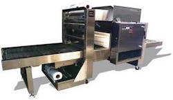
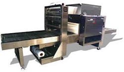
One example of this type of robot is the ROKH Infeed system from Polypack. The company’s pick-and-place system is designed to collate and load multiple products directly from a conveyor onto the shrink-wrap film where several products can be sealed before packing (see Fig. 1).
However, there are many cases in which the precise part location of a product is not known or cannot be made repeatable. In applications such as flexible part feeding systems, inspection of 3-D objects, and bin-picking, vision is being used in conjunction with robotic systems to automate these processes.
Some of the benefits of deploying these systems, says Adil Shafi, president of Advenovation, include labor savings, gains in part production rates, part quality improvements, and multiple product handling capabilities. In developing systems to meet the needs of specific applications, system integrators can choose from a variety of cameras, vision software, and robotic equipment.
To visualize the object that is to be picked, placed, machined, or inspected, several sensor types are available. These include linescan cameras or high-speed CMOS sensor-based cameras that, when used in conjunction with structured lighting, can generate three-dimensional profiles of objects. These imaging systems are useful in applications where the surface or volume of a part must be inspected—for example, in pharmaceutical blister-pack analysis or calculating the volume and thus weight of fish filets before slicing.
Controlling motion
To develop vision-based robotic systems, two basic approaches are used. In position-based visual servoing (PBVS) techniques, features within a specific object are detected and used to create a 3-D model of the environment. In pick-and-place systems, for example, camera systems can be used to image a part from either a camera placed on the robot or from above. Using either grayscale correlation or geometric pattern-matching techniques, features of the object are matched with a known template and the orientation of the object calculated. This information is then transferred to the robot controller, which can pick and place the object.
In applications where these features may not exist or where the system integrator does not wish to match the features, an image-based visual servoing (IBVS) method is most often used. In this method, prior knowledge of the part geometry is necessary and compared with captured depth information. To generate this depth information, a number of different techniques can be used: a single camera mounted on the robot that is used to image multiple views of a part; stereo camera solutions; time-of-flight (TOF) sensors; and structured-light-based cameras.
Integrating both servoing approaches, a third method known as hybrid or 2.5-D visual servo control exploits the fact that two images of the same planar surface in space are related by a transformation matrix. By using image data via PBVS techniques, the rotation of the object can be calculated. Then by using IBVS to generate translation information, rotation and translation information are effectively decoupled, ensuring more accurate robot positioning.
To perform PBVS, IBVS, or 2.5-D visual servoing, a number of different cameras and camera configurations can be used. The simplest of these are single-camera systems that either use a camera or sensor mounted on the robot or above the robot work cell. In single-camera systems, PBVS is most often used along with geometric pattern-matching techniques to estimate the position of the object, because if no model of the object is known previously, no depth information can be computed.
Degrees of freedom
Just as there are a number of different methods to capture and process 3-D images, there are also various robots with which systems are used. Although simpler vision-based automation systems may use 2-D actuators to sort parts, these are not technically robotic systems, since a robotic system is generally defined as one that can move in three or more axes.
As such, industrial robots are generally classified according to the number of degrees of freedom in which they can operate. In three-axes-of-motion Cartesian robots, motion is limited to the X-Y and Z directions. Adding a fourth axis of rotation is used in selective compliant assembly robot arm (SCARA) designs. Here, the robots can move to an X-Y-Z coordinate and the fourth axis of rotational motion is obtained with three parallel-axis rotary joints. Because of this, the arm can move in the X-Y direction but is rigid in Z. This type of motion makes these robots useful in pick-and-place applications where a high degree of precision is required.
Extending this concept further to position a robot arm at any point in space, three additional axes of yaw, pitch, and roll are required. Although five-axis robots may only incorporate two of these axes, more commonly four- or six-axis robots are used for applications such as welding, palletizing, and complex part assembly. According to Steven West, development manager of vision-guided robotics at ABB Robotics, most of ABB’s current robots are of the six-axis type. Mounting six-axis robots on a parallel track enables them to be moved to various positions on the factory floor—for instance, by mounting the robot on an overhead gantry. Because of this added flexibility, the systems are known as seven-axis robots.
Single and dual cameras
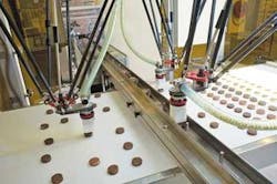
From a system designer’s perspective, the type of image sensor or camera system used with any particular robot depends on the application. In pick-and-place applications, a single camera or smart camera can be mounted above the robotic work cell and used to locate parts as they traverse a conveyor belt. This was the case at Bosch Packaging Technology, a company that was approached by a major European cookie and chocolate maker to improve the efficiency of its factories. In this application, eight robot cells collectively sort 1120 cookies per minute.
As the blister tray passes each work cell, the robot stacks three or four cookies in the appropriate section of the tray. To accomplish this, an XC-HR50 grayscale camera from Sony is installed inside an enclosure at the top of the work cell. As the cookies traverse the conveyor, a 4Sight M embedded vision system from Matrox Imaging triggers the camera and a Meteor-II/Multi-Channel frame grabber acquires images of the cookies. A geometric pattern-matching algorithm then determines the shape and location of the cookies. After image analysis is complete, data is sent to a Bosch Astor delta robot with four degrees of freedom (XYZ and rotational) that picks and places 140 cookies per minute (see Fig. 2).
Single-camera systems are often used to obtain 2-D images of objects or parts; other single and dual camera systems can be used to obtain 3-D information about parts being inspected. At the 2009 Robots, Vision & Motion Control Show, for example, Motoman demonstrated how 3-D information could be obtained by using a single camera mounted to the company’s seven-axis, in-line SIA20 robot. Known as MotoSight 3D, the PC-based system was used to locate randomly stacked parts to be picked up and placed accurately into a press or machine tool.
The camera, mounted on the robot, takes images from multiple locations to evaluate and calculate the location of the part relative to a known location. The system uses 2-D and 2.5-D calculations to refine the search area and then uses a proprietary 3-D algorithm to calculate the final location of the part. At the show, the company demonstrated a pick-and-place machine that used MotoSight 3D to locate stacked parts in 3-D space.
Although a single camera can be mounted to the end of a robot to obtain 3-D information, the most common method of performing this task is by using stereoscopic cameras. This is the method that will be used by Vision Robotics Corp. in a proposed robotic system that will be developed for automated orange harvesting. In operation, scanning heads placed at the end of multiaxis arms will use arrays of stereoscopic cameras to create a virtual 3-D image of the entire orange tree (see Fig. 3).

After stereo images are captured, they are segmented using a Canny edge detector and then spatially matched to calculate the point in 3-D space that corresponds to the matched object. These matches are used to create a 3-D grid. Positions and sizes of the oranges are then stored and their locations passed to the harvesting arms that will then pick each orange efficiently and economically.
Laser scanning
Either a single camera mounted on a robot or dual-camera systems may be accurate for applications such as product sorting and pick-and-placement of parts, but where more robust, shiny and reflective surfaces need to be scanned, system integrators are turning to laser-based scanners. In operation, these scanners project a single light stripe over the part to be examined. By moving either the scanner or part, the structured laser profiles can be digitized and used to generate a 3-D map of the part.
Companies such as SICK USA offer cameras, like its IVC-3-D, that incorporate a structured laser light source within the scanning head. Other products, such as the company’s Ranger camera, can be used with external laser profilers.
Manufacturers such as Orus3-D have also developed integrated laser profiling systems for 3-D imaging applications. Orus3-D’s RoboGauge, for example, features a 3-D laser scanning head, an RT-series vision controller, and an associated software library. Mounted on the end of any industrial robot or multiaxis or gantry system, RoboGauge scans parts and converts the data using proprietary algorithms that produce a representation of the scanned surface. Point cloud data can then be compared with CAD models of the part.
Because of the range of sensor types, robotic systems, and lighting that must be used in these applications, many robot vendors offer a number of methods to support their customers’ applications. At ABB, for example, the company’s PickMaster vision system leverages the PatMax software from Cognex while the company’s TrueView system combines 3-D pattern matching software from Braintech for bin-picking applications. According to West, ABB has also deployed systems using both SICK and Orus3-D laser scanners.
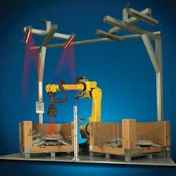
Another method for determining the 3-D position of an object is to incorporate a calibrated laser projection device with a single camera. By calibrating and understanding the geometry between the camera and the laser projectors, the position and tilt (or pose) of the object can be determined. This is the approach used by Fanuc Robotics when performing high-speed bin-picking of parts. In operation, the company’s 3-DL sensor laser/camera is mounted onto the robot’s end-of-arm tool and positioned, using its motion capabilities, above a collection of parts stored in a box, bin, or container. By moving the sensor toward the box, the part position and angular pose can be determined and the part lifted safely from the container.
At the 2009 Robots & Vision show, Fanuc demonstrated this bin-picking capability with a system that removed automotive hub caps from a container. To check for a proper feature of a part, the part held in the robot’s gripper passes a stationary Fanuc iRVision system so that the feature of interest is in the camera’s view (see Fig. 4). A good part/bad part determination of the feature is then made and a pass/fail decision made without adding cycle time.
null
Time of flight
Laser scanners are highly accurate—the accuracy of the RoboGauge system varies between 25 and 200 µm—but that level of accuracy may not always be required in applications such as verifying the proper placement of packages on a pallet (see “3-D measurement systems verify pallet packing,”Vision Systems Design, September 2009). While scanners can be used to perform these tasks, other less expensive, TOF methods using sensors from companies such as ifm efector can be equally effective. TOF sensors provide 3-D information at frame rates by determining both range and intensity at each pixel. These active sensors measure the time taken by infrared light to travel to the object and back to the camera.
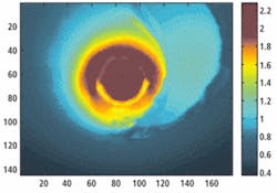
SINTEF has used the TOF approach for a robot developed specifically to perform pipe inspection, replacing the stereo cameras or ultrasound often used for navigation in this type of system. In the design, the robot navigation system uses a Swiss Ranger TOF camera from Mesa Imaging for junction, bend, and obstacle detection. Mounted in front of the pipe robot for navigation, the camera provides 3-D information from the surroundings, which enables a continuous and accurate estimation of junctions and bends in the pipeline (see Fig. 5). Detection of these landmarks in the 3-D images is then performed using algorithms developed by SINTEF.
Advances in sensor technologies and robotic systems have increased the demand for affordable industrial automation systems. These advances have been primarily in the areas of product inspection, placing, and packaging systems; however, combining vision with automated robotic systems will in future see increased interest from nontraditional applications in consumer, automotive, agricultural, and military markets. Likely as not, these applications will also leverage other recent developments in infrared, ultrasonic, and high-speed image sensors as well as mobile robotic systems. For more information on the use of vision in robotics, please register for our recently broadcast webcast at http://www.vision-systems.com/resources/webcasts.
Company Info
ABB Robotics, Auburn Hills, MI, USA
www.abb.com
Advenovation, Brighton, MI, USA
www.advenovation.com
Bosch Packaging Technology
Minneapolis, MN, USA
www.boschpackaging.com
Braintech, McLean, VA, USA
www.braintech.com
Cognex, Natick, MA, USA
www.cognex.com
Fanuc Robotics
Rochester Hills, MI, USA
www.fanucrobotics.com
ifm efector, Exton, PA, USA
www.ifmefector.com
Matrox Imaging, Dorval, QC, Canada
www.matrox.com/imaging
Mesa Imaging, Zürich, Switzerland
www.mesa-imaging.ch
Motoman, Dayton, OH, USA
www.motoman.com
Orus3D, Laval, QC, Canada
www.orus3D.com
Polypack, Pinellas Park, FL, USA
www.polypack.com
SICK USA, Minneapolis, MN, USA
www.sickusa.com
SINTEF, Trondheim, Norway
www.sintef.no
Sony, Park Ridge, NJ, USA
www.sony.com/videocameras
Vision Robotics Corp.
San Diego, CA, USA
www.visionrobotics.com