Software and hardware team for image analysis
Andy Wilson, Editor
Whether the product under development is a mobile-phone camera or a military targeting system, the image sensors must be properly configured to deliver optimum image quality. This requires an accurate characterization of image quality.
Fortunately, recent advances in image-sensor configuration software, image-quality testing software, and the integration of the two has made this process easier and faster. Most image sensor vendors, including Aptina Imaging (San Jose, CA, USA; www.aptina.com), OmniVision (Santa Clara, CA, USA; www.ovt.com), STMicroelectronics (Geneva; Switzerland; www.st.com), and Toshiba (Irvine, CA, USA; www.toshiba.com) offer sensor configuration software that operates with hardware demonstration kits.
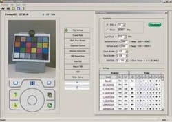
A good example is Toshiba’s ImaTuning software, which allows developers to modify sensor register settings, grouping the registers for a specific image pipeline function in one graphical menu (see Fig. 1). Using this software, developers can visualize changes and interactions between registers in real time when the settings change. This pipeline tuning tool can be used to control functions such as automatic white balance, gamma correction curve editing, edge enhancement, noise reduction, and zoom effects.
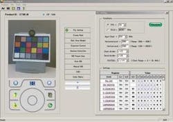
Aptina’s primary application for configuring its image sensors (see Fig. 2) is DevSuite. Like Toshiba’s ImaTuning, it includes common image control functions as well as a feature that allows developers to examine, record/store, and play back combinations of settings. Using this feature, the behavior of a group of sensor registers can be easily manipulated in combination to modify sensor performance, allowing users to enable specific modes of operation with a single mouse click.
To determine whether the registers in the image sensor are correctly configured, an image must be captured and analyzed. This entails using a test chart, such as the X-Rite Color Chart, which contains patches having accurate reference colors that allow color accuracy to be evaluated.
More sophisticated test charts such as the SFRplus chart from Imatest (Boulder, CO, USA; www.imatest.com) contain slanted edges for measuring sharpness and lateral chromatic aberration across the image sensor, horizontal bars for measuring distortion, a step chart for measuring tonal response, and a set of color patches for measuring color accuracy. After a well-focused, uniformly lit, glare-free test chart image is captured by the image sensor, regions within the image can be selected for analysis.
In addition to changing sensor configurations, most vendor-supplied software also allows a limited range of image quality factors to be evaluated. For example, Toshiba’s ImaTuning software contains color tuning, lens shading, and sensor characterization tools. With the color tuning tool, developers can tune the color matrix by matching the target color chart image. Lens shading correction can be performed automatically or manually.
When performed automatically, the correction criteria are set, and then the tool provides real-time measurement of lens fall-off, blemish level, and color uniformity. Sensor characterization parameters such as signal-to-noise ratio, FSR, sensitivity, and linearity can also be measured. Other image sensor vendors offer configuration software that provides a similar set of limited image quality tests.
To analyze image quality in greater detail, engineers import captured images into analysis software and compute metrics such as sharpness, chromatic aberration, distortion, color accuracy, noise, dynamic range, and sensitivity.
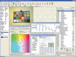
One software package, Imatest’s Image Sensor Edition, analyzes these image quality factors and produces graphical displays, comma-separated-value files, and XML output streams of the test results. The software also offers the ability to load images directly from Aptina’s DevSuite and OmniVision’s OVTA Tool 2009. This eliminates the need to capture images separately and load them individually into Imatest software, speeding the evaluation process.
Imatest has announced plans to extend this image-loading capability to support both Toshiba’s ImaTuning and STMicroelectronics’ configuration software package.
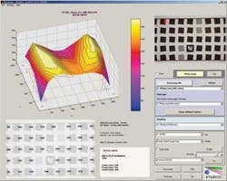
One image quality metric measured in Imatest’s Image Sensor Edition—and one of the best indicators of perceived image sharpness—is the spatial frequency where the modulation transfer function (MTF), i.e., contrast, is 50% of its low frequency value (MTF50). Additional metrics, such as MTF20—the spatial frequency where MTF is 20% of its low frequency value—can also be measured. Depending on user settings, the software can select and analyze from 1 to more than 100 regions of interest (ROI), allowing the sharpness of the entire imaging field of the sensor to be analyzed.
The MTF results can be displayed in multiple forms. In typical multi-ROI results, 13 ROIs (center, corners, partway to corners, left, right, top, and bottom) selected for MTF analysis are shown surrounded by red rectangles where the second and third numbers next to each rectangle correspond to MTF50 and MTF20 measurements (see Fig. 3). While calculating MTF, the software simultaneously computes test results for chromatic aberration, distortion, tonal response, color accuracy, and noise—all from the same SFRplus test image.


