Cylinder Challenge

Winn Hardin, Contributing Editor
Machine-vision integrator MoviMED faced significant challenges when designing and building a high-speed inspection system for gauging metal cylinders.

Among the factors that needed to be addressed were measurement of a 9-mm-diameter cylinder that is 2–3 in. long with micron precision despite mechanical fixtures; triggering from an optical encoder; and cameras with minimum spatial resolutions in the 3–7-µm range. Designers could also expect the ambient conditions to affect cylinder placement: The system would operate in a plant where temperatures vary from 50º to 110ºF and part temperatures vary from 50º to 150 ºF.
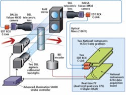
The system integrator assessed the impact of curved surfaces on sub-pixel interpolation and went through an iterative software development cycle to optimize parallel image processing on multicore microprocessors. MoviMED was compelled to design a system that uses specialized high-resolution, global-shutter cameras; Camera Link-over-optical-fiber connectivity; data acquisition and frame grabber boards; and a server running a real-time OS and image-processing algorithms on twin quad-core Xeon microprocessors (see Fig. 1).
A chain wreck
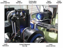
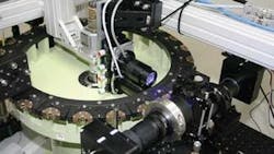
A conveyor chain holds the cylinders as they come down the production line. Rotary turrets propel the chain at rates of 20 parts/s or 52 in./s. Each turret holds 24 cylinders. The machine-vision system is installed on one of the turrets near the end of the production process (see Fig. 2). The MoviMED system is tasked with making several linear measurements, including diameter, length, and other dimensional measurements at multiple points along the cylinder. After the analysis is complete, measurement data are passed to a nearby PLC.
null
Sub-pixel interpolation
“We have a dual camera setup because of the aspect ratio of the part, which is fairly long at 2–3 in., but only 9 mm (0.35 in.) wide,” explains Markus Tarin, president and CEO of MoviMED. To achieve micron resolution at this size, the system would require a 16-Mpixel camera. The camera also needed a global shutter to acquire a blur-free image as the parts move past. Unfortunately, this camera does not exist.
“There also wasn’t a lens that could cover these optical specifications,” Tarin says. “We had to go to our next best option, which was using two cameras and a prism that would allow us to fold the cameras out of the way while allowing us to use the 1x optics that we needed. This complicated the matter because we needed to calibrate two camera imaging spaces and treat them as one. You have to calibrate for multiple axes of freedom between both cameras and account for a small amount of jitter between the two cameras.”
The part is illuminated by two SILL blue LED backlights. An Advanced illumination strobe driver fires the lights at 6 A for 5 µs during each 50-ms part cycle to help “freeze” the part and further reduce blurring caused by motion. Without the short strobe exposure, the 15-µs minimum shutter speed of the DALSA 4M30 Falcon cameras would still blur the images enough to compromise the linear measurements. “SILL had the light we needed, Advanced illumination had the driver, but neither had both. So we had to build some custom hardware to get the two units to talk,” Tarin notes.
Both cameras use 1x lenses, which means the system essentially projects the part at a 1:1 ratio onto the camera’s 7.4-µm-pixel sensor. By using edge detection algorithms with sub-pixel interpolation (included in the National Instruments LabVIEW RT [real-time] image-processing arsenal), Tarin could improve the edge detection by 7 to 10 times, meeting the 1-µm spatial requirement for the imaging system (see Fig. 3).
“This system is all about statistical process control, standard deviation, and repeatability,” Tarin says. “Everyone was expecting a Gaussian distribution of the measurement, but our testing showed that was not always the case. By testing 10,000 parts, we were able to identify the reasons for this unexpected behavior and account for it in the design.”
Timed for success
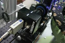
The on-turret hardware includes a BEI optical encoder with 3.5-µm resolution. Although the frame grabbers could accept the encoder signal directly, MoviMED chose to route the encoder signal into the counter/timer input of a National Instruments PCI MIO-6254 multifunction data acquisition board. This was intended to more accurately measure the rise and fall of the quadrature encoder signal and achieve more precise control over the camera trigger timing and pulsewidth. The board reads the quadrature signal and triggers the Advanced illumination strobe controller while passing the trigger signal across a PCI Express bus to two National Instruments 1427e PCIx Camera Link frame grabbers—one for each camera. When the trigger signal fires the cameras, the image data from the cameras are converted from electrical to optical signals using EDT RCX Camera Link-to-fiber extenders (see Fig. 4). Using fiber allowed MoviMED to place the cameras 40 m from the processing server as well as handle the 320-Mbyte/s bandwidth generated by the two 4-Mpixel, 16-bit cameras operating at 20 frames/s.
“Because the parts are circular and come at the cameras on a rounded turret, being a few microns out of position can impact all your other measurements,” Tarin says. “By analyzing the signal from the encoder, we could account for differences in cylinder location caused by the mechanical turret, ensuring that overall system repeatability would be sufficient for the customer’s needs.” The analysis showed that encoder drift was not a problem because the count reset every 360°.
Maximizing multicores
MoviMED’s programmers initially developed the image-processing and communication routines to run in parallel. However, testing on a single quad-core processor showed that this approach would max out two cores, leave a third at 50% and the fourth virtually unused.
“We’re mainly doing edge detection and linear measurements,” explains Tarin. “So we’re trying to balance the image processing, the communications loop, and the math loop across the cores. In LabVIEW, it’s fairly easy to see what code is executing where, although that doesn’t make the balancing act any easier. If you write it in parallel, you still have to move data from one core to another, which can nullify the benefits of multiple cores.”
MoviMED ended up rewriting the code several times, he points out, eventually moving to two quad cores: one for image processing and the other for communications and diagnostics. “What we learned is that, while you still want your code to work in parallel as much as possible, there are still sequential operations that need to happen in a specific order and time. So we had to write the code to be in part parallel and also in part sequential,” concludes Tarin. “It all comes down to the specific components and which algorithms you use. When you’re trying to balance code like this, every system is unique, every system design custom. The good news is that with LabVIEW we were able to move code around and quickly change things. If we had to do this in C, we still wouldn’t be done.”
MoviMED’s system has been fully tested and is ready for installation. A final addition was a cooled hermetic enclosure for the lights and cameras so that large swings in ambient temperature will not impact the system’s measurement accuracy due to the thermal expansion of components and fixtures.
Company Info
Advanced illumination
Rochester, VT, USA
www.advancedillumination.com
BEI Industrial Encoders
Goleta, CA, USA
www.beiied.com
DALSA
Waterloo, ON, Canada
www.dalsa.com
EDT
Beaverton, OR, USA
www.edt.com
FRANZ SILL
Berlin, Germany
www.sill-lighting.com
MoviMED
Irvine, CA, USA
www.movimed.com
National Instruments
Austin, TX, USA
www.ni.com