Targeted Test

Gregory Hollows
System developers can now choose imaging devices that range from those used in inexpensive cell phone cameras to more advanced devices designed for military and astronomical use. With so many choices, it can be challenging to discern what combination of sensor, camera, lens, and lighting components will meet a specific application’s needs. Luckily, a good set of testing targets can allow camera/lens combinations to be evaluated at a fairly low cost relative to the total cost of system development.

One the most commonly used test targets is the USAF 1951 target, which comprises sets of horizontal and vertical lines of varying sizes (see Fig. 1). This target allows an imaging system to simultaneously view a variety of spatial frequencies (line pairs per millimeter, or lp/mm). Each set of lines on the target, referred to as an element, has a unique set of widths and spacings and is identified with a number from 1 through 6.

Six sequentially numbered elements together are considered a group, and each group has an identifying number that can be positive, negative, or zero. Together the group number and element number allow spatial frequency to be determined.
The target is designed so elements increase in frequency along a spiral toward the target’s center, placing higher-resolution elements in the middle of the target. This is beneficial when testing zoom lenses since as lens magnification increases and the field of view is reduced, higher-resolution elements remain within the field of view. This eliminates the need to reposition the target.
However, keeping all the high-resolution elements in the center of test charts can have its drawbacks because lenses produce different levels of resolution as you traverse the field of view from the center toward the corner. In most cases, resolution drops as you move away from the center of the field; thus, it is important to check resolution and contrast levels at various positions.
This checking requires moving the target around the field of view to fully evaluate system performance. The need to reposition the target increases the number of images that require analysis, in turn increasing testing time.
Another drawback of this test is that the target is only focused at discrete positions. Therefore, it is difficult to determine when the entire field of view is in best focus. Some lenses obtain very high resolution in the center but very low resolution in the corner when the lens/camera system is focused on the center of the image. A slight defocusing of the lens can balance the resolution across the field, although usually to the detriment of the center resolution. This loss of center resolution is not necessarily bad, however, because the lens could very well still meet the demands of the application even when defocused.
The potential for variability in resolution across the field of view reinforces the need to analyze all field positions before drawing conclusions on a system’s performance. The lens that performs optimally with the target at the center may not perform the best overall. It is critical when using this testing method to perform all of the analysis at a single focus setting.
It seems intuitive to determine the system’s best performance through the middle of the lens and then refocus to see the best performance in the corner. However, this will not show how the system will perform once deployed since refocusing during operation will probably not be possible.
Ronchi rules
Some of the issues associated with the USAF target can be overcome using a different target, known as the Ronchi ruling. This target consists of repeating lines at one spatial frequency, running in one orientation that covers the target’s entire surface (see Fig. 2). Because there is detail across the entire target, the system’s best focus across the entire field can be determined simultaneously.

There are two drawbacks to using the Ronchi ruling. First, since a given target provides only one frequency, a different target is required for each frequency that needs to be evaluated.
Second, because lines only propagate in one direction, nonsymmetrical resolution reductions across the field due to factors such as astigmatism cannot be analyzed. To overcome this, the target must be rotated by 90° and a second image also used to analyze the resolution.
Combined strengths
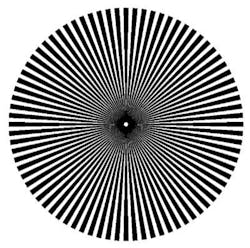
A third type of target—the multielement star—provides a fairly robust option that combines many of the strengths of the USAF and Ronchi targets. Each element of the star target consists of a circle formed of alternating positive and negative pie-shaped wedges tapering toward the center at a known angle (see Fig. 3). The element’s tapering wedges provide a continuous change in resolution that can be evaluated in both the vertical and horizontal direction along with a variety of other orientations without repositioning the target.
Having many stars across the field of view allows the best focus across the field of view to be determined while simultaneously analyzing horizontal and vertical information at a variety of resolutions (see Fig. 4). Visualizing all of this information simultaneously allows fast comparisons between two different imaging solutions to be made.
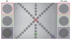
FIGURE 4. The multielement star allows resolution to be evaluated at a range of frequencies for multiple axes at a point in field of view without requiring target rotation. Closeup comparisons from the center, bottom edge, and corners of the images show how two different lenses can perform at different resolutions while including directionality.
As with the other targets, the star target also has its drawbacks. Because the resolution changes that the wedges provide are continuous, not discrete as in the other targets, it is more difficult to determine the exact resolution that the test system is achieving at each element.
Additionally, the star elements’ circular nature and the nonsymmetrical blurring that can occur make it more difficult to use simple software tools such as line profilers to extract information from the image. Making full use of the star target thus requires relatively more demanding image-analysis software programming efforts.
Methods for system bench testing using these imaging targets can help guide the selection of sensor/lens and camera combinations; nevertheless, it is critical to understand the pros and cons of these techniques to avoid misinterpreting test results. It is also a good idea to employ image-analysis software because this will provide a more reliable interpretation of results than the human eye.
Gregory Hollows is director, machine vision solutions, at Edmund Optics (Barrington, NJ, USA; www.edmundoptics.com).
More Vision Systems Issue Articles