Defect Avoidance
Machine-vision system catches defects in seamless steel tube production using linescan cameras and near-infrared imaging
Winn Hardin, Contributing Editor
At its production plant in Austria, voestalpine Tubulars uses the CPE push bench process to manufacture seamless steel tubular products up to 7 in. in diameter for a variety of uses, including pipe and tube goods used in the petroleum industry. A machine-vision defect inspection system has been installed to check the products during this production process.
The push bench process starts with a billet of steel heated to 900°C or more. The billet is pierced through the center to create the inside of the tube, and a mandrel pushes the billet through a series of fixed metal rollers. Each consecutive set of rollers is constructed so that the opening between the three rollers grows smaller and smaller. As the mandrel pushes the steel through the rollers, the outer diameter of the billet shrinks, while preserving the interior hole. Eventually, the billet becomes a seamless tube built to a customer-specified length.
Rollers can become damaged over time. In some cases, a roller will develop a surface crack. Hot metal from the tube is pushed into the crack, leaving a defective surface void on the steel tube. Also, the metal pushed into the crack can be deposited on later tubes, leaving a “bump” defect on the surface. Both are unacceptable.
Locating these defects early in the process allows voestalpine Tubulars to identify cracked rollers and replace them before they render tens or hundreds of meters of steel tubes defective. To develop the inspection system, the company turned to the machine-vision department of PROFACTOR, which was formerly the machine-vision department of the Austrian research center Forschungsförderungsfonds der Gewerblichen Wirtschaft (FFF).
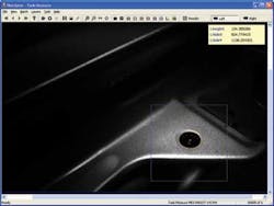
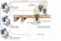
voestalpine Tubulars contracted PROFACTOR to develop an inspection system to locate the surface defects immediately after the steel tube emerges from the final set of rollers, while the steel tube is still 900°C, and in ambient temperatures of 50°C (see Fig. 1). After evaluating both visible and infrared spectrum solutions, PROFACTOR built the broken roll detection system using three Basler L103b-2k linescan cameras with LVDS output and F-mount to capture the tube’s entire circumference.

The cameras are connected by 200 m of optical fiber to three PCs that process the images to locate blobs indicating surface defects. The information is stored locally, as well as sent to the plant network to quickly alert quality control personnel that a roller has become defective.
The project plan
The broken roll detection system took three years to develop and install at the voestalpine Tubular facility. Gerhard Traxler, machine-vision engineer at PROFACTOR, developed a three-phase project. During the first year, PROFACTOR engineers developed a series of proof-of-concept systems that used both visible-light CCD cameras and infrared cameras to see if it were possible to identify surface defects in the steel tubes by detecting localized changes in the surface temperature.
Traxler notes that it took longer to test various solutions because a defective roll may not appear for weeks or months and collecting the sample data took time. As a result of these tests, PROFACTOR decided to install the three 2048-pixel L100b linescan cameras in a water-cooled housing after the bench push system, just 15 m after the tube emerges from the final set of rollers.
“Since CCD cameras are sensitive only up to a wavelength close to 1 µm, we had a poor signal in relation to midwave cameras,” explains Traxler. “Actually, we use the NIR range of light because, according to Planck’s law, most of the energy produced by a 900°C hot body is emitted in the IR range. Even if visible cameras are more sensitive in the green spectrum, most of the signal that is captured from a radiating hot body lies in the NIR range of light. Therefore, a filter isn’t necessary.”
He adds, “Since thermal cameras with such a resolution and a scan rate of 10-kHz line frequency are not available, and other solutions such as midwavelength cameras would be too expensive, we solved the detection problem with high-end CCD cameras with BIC module to convert to a LVDS signal. We used F-mount Nikkor 135/2.8 lenses, which work well in the NIR.”
The pipe moves at 6.6 m/s; defects are measured in millimeters. The combination of these two factors results in images that are 600 Mbytes or larger for a single tube, which, in addition to electromagnetic interference from the nearby heat sources and the distance to the three PCs, dictated the use of fiberoptic cabling between cameras and PCs. Signals between the cameras and PCs are sent across Arvoo Imaging L2f/F2L-mm optical fiber transceivers—which include an RS-232 channel for connecting to the camera—to a DALSA PC-DIG frame grabber for LVDS signal processing (see Fig 2).
“As you can see in the images,” says Traxler, “we had to do a lot of preprocessing to get an image with usable contrast. The calculations are done by three PCs, which are working in parallel to manage 1 Gbyte of data per tube in production real time.”
The second year of the project was spent selecting the processing steps and developing the algorithms necessary to separate a defective blob from thousands of smaller blobs that are caused by tinder creation on the red-hot tube as it is exposed to the atmosphere. Traxler developed the image-processing chain using a combination of offline and online collected data.
Find the defect
Locating small variations in temperature along the length of a 60-m, red-hot tube is very difficult, especially when the false positives or hot spots created by specks of tinder outnumber real defects by thousands to one.
The processing begins with image capture, which is triggered by an ODML 600 IR photoelectric sensor from Trenka Industriebedarf located at the inspection station. Images from two of the cameras are passed to the one PC that has a dual-core processor, while the third camera sends its information to a second PC, running the same image-processing software as the first PC (see Fig. 3).
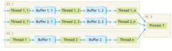
“There was simply too much image processing to do on image files as large as 1 Gbyte for a single PC to perform,” says Traxler. “So we decided to use a dual-core PC to process images from two of the cameras, and a second PC to process the third camera. A third PC acts as the user interface, collects results from the other two PCs, and communicates the findings back to the production control room.”
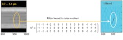
The image-processing software developed by PROFACTOR in C++ first truncates the full linescan image to the length of a single tube. Traxler’s software then uses edge detection to locate the diameter of the tube and further reduce the data set. Another algorithm aligns the edges from one frame to the next individually for each camera; alignment is necessary because the tube bounces as it is pushed by the mandrel along the supporting rollers. A proprietary algorithm enhances the contrast of the near-infrared image before a binarization algorithm segments the image (see Fig. 4) to isolate pixels with intensities above a set threshold.
Blob capture
After potential defect areas have been enhanced in the image, PROFACTOR performs a blob analysis to evaluate whether pixels of higher-than-normal intensity represent tinder or defects. Because of the diameter of the pipe and the fact that cracks in the rollers occur perpendicular to the tube’s length, the vision system looks for groupings of pixels between 450 and 900 mm, and oriented across the tube’s width.
“Because we are working with sets of coordinates—we don’t have any pixels at this stage any more because periodicity is calculated based on the position of the blobs only—in multiple dimensions rather than single data points in a single dimension, we felt a fast Fourier transform (FFT) wouldn’t work for this application, plus it would require a huge amount of processing on datasets up to 1 Gbyte in size,” noted Traxler. “As it is, we made every effort to reduce the dataset as early in the inspection procedure as possible.”
The inspection system may go days, weeks, or even months before identifying a broken roll. And yet the cost of not locating defective rolls until the tube has cooled and can be manually inspected means that the manufacturer may have to throw away hundreds of meters of steel tubes at a cost of many thousands of dollars.
When a defective roll is identified, an alarm message is sent from the third PC to the control room where maintenance personnel can immediately halt the line and inspect the rollers for cracks. Up to 50 images are stored locally on the PC in a rotating buffer, and all results, including a table of blob data, are stored locally as well as sent across the plant network for archiving.
“For the next version of the system, we plan to update some components, such as the PCs and possibly the cameras, to benefit from the component development that has taken place since we first launched the system,” concludes Traxler. “In the meantime, we have already developed software for faster processing of image data, and we are discussing if we should transfer the evaluation software into the new frame.”
Company Info
Arvoo Imaging Products
Montfoort, the Netherlands
www.arvoo.com
DALSA
Waterloo, ON, Canada
www.dalsa.com
Nikon
Tokyo, Japan
www.nikon.com
PROFACTOR
Steyr-Gleink, Austria
www.profactor.at
Trenka Industriebedarf
Handelsgesellschaft
Vienna, Austria
www.trenka.co.at
voestalpine Tubulars
Kindberg, Austria
www.vatubulars.com