MEASUREMENT & GAUGING: Profile sensor embeds structured laser and camera
In many noncontact measurement systems, structured laser light is used to illuminate an object as it passes along a conveyor. By capturing the two-dimensional profile of the reflected laser light at specific intervals, measurements of the object’s 2-D profile and shape can be made.
“Although many structured light systems can use the motion of an object on a conveyor to build a three-dimensional map of the object,” says Michael Snow, product manager of Bytewise Measurement Systems–Sensors Division (Columbus, GA, USA; www.bytewisesensors.com), “many manufacturing metrology applications do not require this type of analysis.” In systems for thickness, step height, width, angle, gap, and radial part measurement, for example, determining the 2-D profile of structured light projected on the part can be used to replace more conventional caliper-based approaches to parts measurement.
To build this type of system, developers can employ either structured laser light systems coupled with standalone CMOS or CCD-based cameras or precalibrated systems that integrate both the laser light and camera systems into a single device. Taking the latter approach, Bytewise has developed its CrossCheck laser profile sensors. “In doing so,” says Snow, “we understood the need to develop a lower-cost 2-D profilometer that could be used by research and development, engineering, production, quality, and maintenance personnel to validate product dimensions and tolerances.”
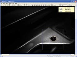
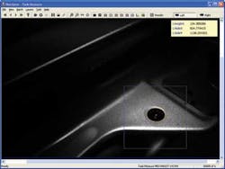
To accomplish this, Bytewise has designed the CrossCheck system with an embedded structured laser line to illuminate the part under test (see Fig. 1). Reflected laser light from the part is then digitized using an embedded camera. “Since both the structured laser light source and the camera are precalibrated and integrated in the same housing, there is no need for the user to geometrically calibrate the system,” says Snow.
Since the embedded camera runs at 30 frames/s, the sensor is not designed for applications such as tire scanning. However, the system can be used to replace manual gauges such as calipers to measure a part’s shape-based parameters such as thickness, step height, width, angle, and radius.
“Eliminating handheld gauges and generating automatic reports for part tolerance increases throughput and reduces human error, especially when non-rigid parts need to be analyzed,” says Snow.
To allow the system to generate these measurements, laser line profile data are transferred to a host Windows XP-based controller over the camera’s FireWire interface. Here, the centroid of the reflected Gaussian curve is used to compute the peak at each point along the reflected laser line profile. Once computed, the data are then used to create a profile of the part that can be displayed on the monitor of the system controller.
Rather than use the data to generate a 3-D profile of the object, Bytewise calculates the 2-D aspect of the specific feature or shape required. CrossCheck software updates the calculated dimension with every profile taken and pass/fail alarms continuously alert the operator to parts that are out of tolerance in the production cycle.
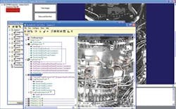
To enable the operator to perform these measurements, CrossCheck software provides users with simple to use “shape tools” that act as virtual micrometers (see Fig. 2). These are used to fit captured data to a circle, rectangle, vertex, line, gap, bump, or step changes and set part tolerances. A master profile comparison tool can then be used to capture a part’s profile to specific break points and guarantee that the shape of a part stays within the desired profile limits.
FIGURE 2. To allow the operator to measure parts, CrossCheck software provides users with simple-to-use shape tools that act as virtual micrometers. These are used to fit captured data to a circle, rectangle, vertex, line, gap, bump, or step changes, and set part tolerances.
In independent tests, measurements made with the CrossCheck were compared with those made using Absolute Digimatic mechanical calipers from Mitutoyo (Kawasaki, Japan; www.mitutoyo.co.jp). According to Snow, these tests revealed that the standard deviation between measurements was three to four times lower using the laser scanner.


