Finding Faults in Finished Wood Surfaces
Finished wood surfaces are analyzed for defects using off-the-shelf cameras, frame grabbers, and lighting products
Clemente Marín Romero and Jose Caballero Aroca
Characteristics such as knots, irregular cell groups, fiber deviations, and color variations are commonplace in wood and the products manufactured from them. Because of the large number and type of variations found in this natural material, many natural woods are considered undesirable in certain furniture products where manufacturers are required to produce multiple products with consistent finishes.
To manufacture these products, companies often turn to particle board or fiber-based materials. However, even in developing such products, manufacturers cannot guarantee the total absence of surface faults that may appear due to coatings of paint, varnish, melamine, or paper.
Indeed, one of the most critical processes in the furniture industry is that of applying coatings to these wood products in the form of varnish or paint. If incorrectly performed, this can lead to a large number of products that need to be recycled.
In turn, this increases the time and cost of manufacturing and the cost of the finished product. These kinds of varnishing faults are extremely difficult to see, particularly when such finishes are transparent. To asses such products manually is made more difficult because faults are highly specular and thus dependent on the type of lighting used.
In Northern Europe, machine-vision systems have been used to assess the faults in wood finishes. However, many of the systems use gray-level machine vision, which is usually inefficient at detecting color changes across the face of the finished products.
Where color cameras, lasers, and spectrometers are used to measure the intensity and color of the reflected light, characteristics such as knots, cracks, color changes, and fiber deviations can be found. These systems can prove unreliable especially in cases where different wood species are used or where variable surface roughness may be present. In the case of painted, varnished, or lacquered wood surfaces, very few commercial machine-vision systems can detect surface faults such as craters, pinholes, blistering, wrinkling, and peeling.
Controlling conveyors
To allow the defects to be detected, the Technological Institute of Optics, Color and Imaging (AIDO), in conjunction with a number of other organizations (see Acknowledgment), has designed a machine-vision system that automatically detects and classifies faults in coated wooden products. These data are then used to isolate the problems that may be causing these faults and to notify an operator so that further losses in manufacturing may be reduced.
Because of the variety of faults that need to be detected, the VAMAD system comprises three work cells, each composed of a grayscale camera and four LED bars that illuminate the wood scene from four different angles (see Fig. 1). Synchronization between the cameras and the lighting systems is accomplished using three LED lighting controllers, each of which synchronizes a camera with its four corresponding LED bars.
In operation, each 96-frames/s camera captures four pictures with a different angled illumination, and a previously trained multi-image algorithm detects and classifies the faults in the finished wood surface.
Because of the speed of the conveyor belt, it is necessary to trigger the camera and illumination system as the wood passes through the imaging station. As the laminated wood passes along the conveyor belt, an integrated DRS61 encoder from SICK is used to measure the movement of the conveyor belt. Digital data from this encoder are then transferred to a host PC controller using a PCI 6602 digital I/O board from National Instruments.
After the PCI 6602 board counts a specific number of pulses from the encoder, it triggers four LDL-180X16-SW white bar lights from CCS America to operate in stroboscopic mode through a PP820 LED lighting controller from Gardasoft.
Image acquisition
To acquire four images in every imaging work cell, the PCI 6602 generates signals that are captured by three Matrox Helios frame grabbers, each of which triggers one of the cameras and its corresponding four-LED lighting system through the Gardasoft lighting controller (see Fig. 2). Since the camera features a rolling shutter, the wood product must only be illuminated for 2 ms when the shutter is open to avoid deformations in the captured image. As a consequence of this low exposure time, the cameras need to acquire the highest amount of light in a short period of time and thus are equipped with optics featuring an f/1.4 aperture.
The four consecutive images are then imaged by a single 96-frame/s, 2352 × 1728-pixel A-404k CCD Camera Link camera from Basler. Images are transferred to the host PC using a Helios Full Base camera-to-computer interface board from Matrox Imaging. In operation, the operator can visualize in real time the four pictures as they are captured by the system.
After images are captured, they are processed by the system’s host PC. To analyze defects within the series of images, it is first necessary to accurately register the images since each of the four images is taken at 2-ms intervals.
Because the speed of the conveyor and the exposure time are known, this task is accomplished simply by clipping different portions of the image to retain only those areas of the image common to all four images. In this way, the movement of the conveyor belt is compensated.
After clipping, a composite of the four images is made and an algorithm compares the different shadows that the four LEDs placed at different angles have produced on the finished wooden surface. Then, if the system has detected a fault, it classifies the fault and displays the information to the operator on the PC’s monitor.
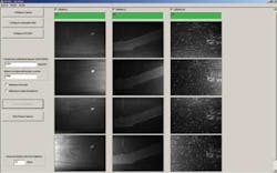
In developing the user interface for the VAMAD system, it was necessary to allow the operator to alter the different parameters of the system for various types of finished wood (see Fig. 3). This includes changing camera parameters such as exposure time and speed, configuring the timing of the LED lighting controllers, and defining the parameters of the digital I/O board used to control the camera and lighting synchronization.
FIGURE 3. Four images taken at different angles from three different work cells are displayed on the operator’s monitor. From here, the operator can also alter the different parameters of the system to analyze various types of finished wood.
After configuring the parameters for different types of finished wood products, the operator can run the application, start acquiring and processing images, and evaluate whether the possible faults present in the wood. Once these parameters are programmed correctly, the system can run automatically.
Acknowledgment
This work was performed as a collaboration between the Technological Institute of Optics, Color and Imaging of Valencia (AIDO; Valencia, Spain; www.aido.es), the Technological Institute of Furniture, Wood, Packaging and Derivatives (AIDIMA; Valencia, Spain; www.aidima.es), the Industrial Association of Navarra (AIN; Navarra, Spain; www.ain.es), the Technological Center for Wood Technology and Furniture (CETEM; Yecla, Spain; www.cetem.es), and the Institute of Industrial Information Technological (IIIT) at the University of Karlsruhe, Germany (www.iiit.kit.edu, www.uni-karlsruhe.de). The VAMAD project has been funded by the Consorcia Program of the Ministry of Industry, Tourism and Commerce of Spain and the resulting system has been patented.
Clemente Marín Romero and Jose Caballero Aroca are staff members at Technological Institute of Optics, Color and Imaging (AIDO; Valencia, Spain; www.aido.es).
Company Info
Basler
Ahrensburg, Germany
www.baslerweb.com
CCS America
Burlington, MA, USA
www.ccsamerica.com
Gardasoft
Cambridge, UK
www.gardasoft.co.uk
Matrox Imaging
Dorval, QC, Canada
www.matrox.com/imaging
National Instruments
Austin, TX, USA
www.ni.com
SICK
Waldkirch, Germany
www.sick.com
Technological Institute of Optics, Color and Imaging
Valencia, Spain
www.aido.es


