Capture the Speeding Web
Andrew Wilson, Editor
Just a decade ago, very few vendors provided linescan cameras. Today, more than 30 linescan camera vendors offer products that allow system developers to capture monochrome and color images. By using these cameras in solar panel, sheet metal, wood, and agricultural inspection, in-line quality control systems can be designed to analyze and sort products by making pass/fail/rework decisions.
Just as choosing an area-array camera requires a firm understanding of the camera sensor, clock rate, speed, interface, and optics, so too does specifying a linescan camera for a particular application. Of course, there are differences. In an area-array camera with square pixels, for example, achievable resolution is dependent upon the pixel size of the sensor and optics used.
In a linescan camera, achievable resolution is specified in one single axis, parallel to the image sensor, commonly known as the cross web-axis. Like area-array cameras, the achievable resolution of a target image in this axis is dependent upon the pixel size in the linear array and the resolving power of the lens. Assuming there is no cross web motion of the camera or material being inspected, then according to Nyquist criteria, the maximum achievable resolution of a sensor that features 14 × 14-μm square pixels and a lens with 1:1 magnification will be 28 μm across the web.
Down the web
To obtain two-dimensional images using a linescan camera requires either motion of the linescan camera down the web or, more commonly, motion of the web itself. This “down-web” resolution is dependent on the camera optics, clock rate, and speed of the web. For a 1k × 1-pixel linescan camera with a clock rate of 36 kHz and 14-μm square pixels imaging a web with a speed of 36,000 m/s, the down-web resolution will be 1 m. More realistically, a web moving at 3 m/s will achieve a down-web resolution of 83 μm, significantly larger than the pixel size of the camera used.
Vision system developers must automatically accommodate for any difference in web speed that may occur. If web speed variation occurs, then down-web resolution will vary across the reconstructed image, making any image measurements inaccurate. To compensate for this, output from an encoder that measures web speed can be used to dynamically adjust the camera’s line rate during image acquisition. If the web moves more slowly, the line rate can be reduced; if the web moves more quickly, this line rate is increased. In this way, the same down-web resolution is achieved irrespective of the speed of the web.
However, reducing or increasing the camera line rate when in free-running mode directly increases or reduces the camera exposure time, resulting in brighter or darker images being captured. Most linescan cameras incorporate an electronic shutter that allows the exposure time of the sensor to be adjusted, regardless of the camera line rate.
For cameras that do not incorporate electronic shutters, other methods exist to compensate for web motion. In 2006, Euresys introduced a method known as Advanced Downweb Resampling (ADR), which allows a linescan camera to be operated at a fixed line rate without an electronic shutter. While a motion encoder is still used to accurately monitor web motion, the measurement controls a patented interpolating device that resamples the data from the camera producing an image of uniform resolution (see “Resampling compensates for speed variations,” Vision Systems Design, February 2006).
Increased rate
Because line rate plays an important role in determining the down-web resolution, many linescan camera manufacturers have sought methods to increase this rate, while at the same time maintaining high sensitivity and low noise. In some monochrome linescan implementations, for example, single-tap linear imagers are often used. In these cameras, each photosite of the linear CCD or CMOS array converts incoming photons to electrons that are then clocked through a single output or tap.
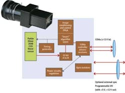
In its LW-PE-2048-1394 linescan camera, for example, ISG uses a 2k × 1-pixel CCD linear sensor from Perkin Elmer to achieve a line rate of 18 kHz with a pixel clock rate of 40 MHz. This line rate allows the camera to output 12-bit pixels at 18 kHz over a FireWire interface. Like many of the company’s cameras, the LW-PE-2048-1394 also incorporates an on-board FPGA that is used to perform offset and gain correction as well as allowing custom algorithms to be added (see Fig. 1).
To increase the speed of this output, linescan camera vendors use multitap CCD or CMOS imagers in their designs. The sensors incorporate two, four, eight, or more taps that increase the camera line rates by these amounts. Multitap designs can be implemented in a number of different ways by system integrators.
In dual-tap implementations, for example, each alternating photosite can be clocked through two different shift registers. Thus, while the clock speed of the imager remains constant, the line rate is doubled. The Sprint family of linescan cameras from Basler employs dual CMOS imagers from 2k to 8k pixels and line rates from 39 to 140 kHz. In dual-line mode, a two-line “frame” of 8k × 2 pixels can be captured at 70 kHz, resulting in an effective line rate of 140 kHz. Architectures like these can also be used in a time-delay summing mode to improve signal-to-noise ratio by nearly 3 dB while maintaining a 70-kHz scanning rate.
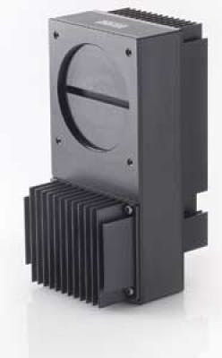
Whatever multitap design is used, the result is an increased data rate. This mandates the use of high-speed interfaces such as Camera Link. Like Basler, e2v uses this interface in its AViiVA UM8 CL 12k × 1-pixel linescan camera, which incorporates a linear CCD with eight taps, each of which are clocked at 40 MHz (see image on p. 33). Alternate pixels from four stages of the CCD are each clocked into two taps, resulting in an eight-tap camera with a line rate of 24 kHz. Like other very high-data-rate linescan cameras, the AViiVA UM8 CL features an on-board FPGA that performs correlated double sampling and flat-field correction.
In free running mode, increasing the camera line rate can increase the down-web resolution of a vision system. At the same time this will limit the number of photons captured by the imager, resulting in a darker image. To obtain consistent image data, an electronic shutter is used to increase the exposure time of each photosite, irrespective of the data rate of the camera line rate. This presents the system integrator with a down-web resolution/exposure tradeoff that must be carefully balanced depending on the type of material and speed of the material that must be inspected.
More light
In determining whether web inspection can be performed at high speed, illumination plays a key role since increased light levels allow faster camera line rates and slower shutter speeds to be used. Realizing the need to capture as much light as possible, a number of manufacturers have introduced time delay integration (TDI)-based linescan cameras. While traditional linescan imagers use a single row of photosites, in configurations such as 2k × 1, 4k × 1, and 8k × 1 pixels, TDI devices add a number of integration stages that allow more light to be integrated from a scene.
When operating in configurations such as 2048 × 96 pixels, for example, the down-web motion must be scanned by the TDI imager at the same rate that the device’s vertical shift register moves the signal charge. This produces an effective increase in the integration time of the sensor, leading to increased sensitivity and lower noise.
According to John Gilmore, image sensor manager at Hamamatsu, the practical limit on the number of TDI stages is determined by the accuracy of synchronization between the vertical-shift frequency and the velocity of the web. Here, for example, a 2–4% scan-velocity mismatch is acceptable for 96-stage TDI devices used for semiconductor inspection (see “CCD advances improve TDI imaging techniques,” Laser Focus World, January 2007).
As one of the highest-resolution TDI cameras commercially available, the Piranha HS 12k camera from DALSA features a 12k × 256-pixel TDI imager, a maximum line rate of 90 kHz, and a throughput of 1.12 Gpixels/s (see Fig. 2). To transfer data from this camera to the PC, DALSA recently announced a new digital camera interface dubbed HSLINK and the Xcelera HS PX8, an x8 PCI Express frame grabber board (see “Facing Interfaces,” Vision Systems Design, January 2010).
Building on the concepts used in the Camera Link standard already adopted by numerous camera and frame grabber manufacturers, the HSLINK standard is set to become the next high-speed interface adopted by the Automated Imaging Association. A further description of this forthcoming standard is described by Steve Kinney, director of technical pre-sales and support at JAI, in his webcast “Developments in Camera Link and other High-Speed Interfaces” (see http://bit.ly/9ZXcFb).
Color capture
While many web applications demand fast multitap linescan and TDI-based cameras, other applications such as agricultural inspection require the use of color linescan cameras. Here again, a number of different linescan imager architectures are finding their way into the latest color linescan cameras. Each of these implementations has its own specific tradeoffs in terms of color separation, spatial resolution, and sensitivity.
To attain the highest degree of color separation, spatial resolution, and sensitivity, for example, a number of companies offer prism-based cameras. By splitting the light into individual overlapping components, three linear monochrome CCD or CMOS imagers can be used to capture the RGB components. Since no color filters are used on the photosites to separate the color components, there is little light attenuation. At the same time, spatial resolution and color fidelity are increased, at the expense of the cost for the size of the optics and alignment required.
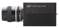
Taking this concept one stage further, the JAI LQ-200CL camera uses a beamsplitter prism to simultaneously capture red, green, blue, and near infrared (NIR) data using four linear CCD arrays (see Fig. 3). Each of the four CCD sensors provides 2k × 1-pixel data at a maximum scan rate of 19 kHz with a 40-MHz pixel clock. The camera then outputs 4 × 8 bits or 4 × 10 bits of image data through a Camera Link interface. A binning function can also be used to combine the values of two adjacent pixels at the output stage, resulting in a doubling of the sensor sensitivity.
FIGURE 3. JAI’s LQ-200CL uses a beamsplitter prism to simultaneously capture red, green, blue, and near infrared (NIR) data using four linear CCD arrays. Each of the four CCD sensors provides 2k × 1-pixel data at a maximum scan rate of 19 kHz with a 40-MHz pixel clock.
To reduce the cost of color linescan cameras, many manufacturers use linear CCD or CMOS imagers that incorporate RGB image filters placed repetitively along the photosite array. Although combining each RGB triplet results in a color pixel value, spatial resolution will be reduced by one-third because three adjacent pixels are require to generate each color pixel value.
An alternative technique is used by DALSA in its dual-color linescan cameras. Alternate red and blue filters are used to generate color pixels on one line of the linear image while a green filter is placed in a second line. DALSA Spyder3 Color uses this technique in its 2k × 2-pixel, two-tap, 18-kHz color linescan camera that is based on the Spyder3 dual linescan monochrome camera. With a GigE Vision interface, the Spyder3 Color can output RGB, RG/BG, or G only to meet different imaging requirements.
One of the main reasons for the development of these dual-color linescan cameras is that the color output more closely mimics the human eye’s increased sensitivity to green light. This is a technique most often used in area-array imagers that employ the Bayer pattern to allocate twice as many green photosites to the green channel. In color linescan implementations this is done at the expense of creating two focal planes in the camera.
Three monolithic linear arrays that respectively employ R, G, and B filters are also being used in color linescan cameras. Devices such as the KLI-2113 CCD from Kodak feature three 2k × 1-pixel arrays, one for each primary color channel. With a square pixel size of 14 μm, the inter-array spacing of each of the three arrays is 112 μm or eight effective lines (although on the data sheet this specification is given as 112 mm—larger than the imager length itself!). Basler has used this device in its color Runner camera, the ruL2098-10gc, that offers a line rate of 9.2 kHz and GigE Vision output.
In the design of trilinear color linescan cameras, it is important to minimize the distance between the rows of RGB linear sensing elements to reduce any image artifacts that may occur when the sensor is used in high-speed applications. In considering a color linescan camera for industrial systems, this spacing should be as low as possible. e2v, for example, has reduced this spacing to 10 μm between each row in its EliiXA trilinear (RGB) and quadrilinear (RGB and NIR) cameras that use CCD imagers of 4k × 3 or 4k × 4 pixels running at 18 kHz (see “Sensors/cameras shine at Vision 2007,” Vision Systems Design, January 2008).
Beyond the visible
While many linescan cameras are used to capture images in the visible spectrum, the need to monitor or sort defects in glass manufacturing, paper, and solar wafer production demands the use of linear IR and x-ray based cameras. To address IR applications, a number of different manufacturers offer cameras based on spot scanning detectors, focal plane arrays (FPAs), and linear IR detectors (see “Industrial Strength Infrared,” Vision Systems Design, April 2010).
A number of linear x-ray CMOS imagers are also available that allow x-rays to be converted into visible light. Imagers from X-Scan Imaging, for example, have recently been used in a system to generate a two-dimensional map of the tread, beads, and sidewalls of tires (see “X-ray Vision,” Vision Systems Design, April 2010).
A-Z of linescan camera manufacturers
Editor’s note:This list is provided as a service to our readers. Please report any omissions to Carrie Meadows, Managing Editor at [email protected].
Basler
www.baslerweb.com
BAP Image Systems
www.bapis.de/en
Chromasens
www.chromasens.de
DALSA
www.dalsa.com
e2v
www.e2v.com
Entwicklungsbuero Stresing
www.stresing.de
Eureca Messtechnik
www.eureca.de
Fairchild
www.fairchildimaging.com
Goodrich
www.sensorsinc.com
Hamamatsu
jp.hamamatsu.com
ISG
www.isgchips.com
I2S
www.i2s-linescan.com
JAI
www.jai.com
KHS Instruments
www.khs-instruments.com
Lord Ingenierie
www.lord-ing.com
Mightex Systems
www.mightexsystems.com
NED
www.ned-sensor.co.jp
NET GmbH
www.net-gmbh.com
Newton Research Labs
www.newtonlabs.com
Opti-sens
www.opti-sens.com
Perkin Elmer
www.perkinelmer.com
Princeton Lightwave
www.princetonlightwave.com
DIAS IR Systems
www.dias-infrared.com
Sentech
www.sentechamerica.com
Schäfter + Kirchhoff
www.sukhamburg.de
Soliton Technologies
www.solitontech.com
Tattile
www.tattile.com
Tichawa
www.tichawa.com
Toshiba-Teli
www.toshiba-teli.com
TVI Vision
www.tvivision.com
Xenics
www.xenics.com
X-Scan Imaging
www.x-scanimaging.com
