Imaging the Flow
Andrew Wilson, Editor
Thanks to innovations in CMOS imagers, solid-state memory, and high-speed data interfaces, today’s solid-state cameras are capable of capturing images at very-high data rates. Often achieving frame rates greater than 10,000 frames/s, these solid-state cameras are now being used in applications ranging from missile testing to the analysis of broadcast sports events.
For scientists and engineers wishing to discover the mechanisms behind events such as the functioning of a combustion engine or the airflow across an insect’s wings, these cameras have become invaluable. To achieve their goals, high-speed cameras deployed in Particle Image Velocimetry (PIV) systems can be used to map the particle flow across or through an object. In this way, the mechanism by which the flow interacts with the object can more easily be understood.
Seeding particles
In PIV, a fluid or gas is first seeded with particles whose motion models the dynamics of the scene. Choosing the particles used is highly application dependent since the particles should be small enough to truly follow the flow of the liquid or gas and large enough to scatter enough light. Furthermore, the choice of what tracer particle to use is dependent on the nature of the gas or liquid used. For these reasons, researchers generally use polystyrene particles, hollow silver-coated glass spheres, and other neutrally buoyant particles for seeding liquid flows; and for gas flows, droplets of atomized liquids ranging from water to oil with 1–10-μm diameters are used.
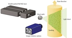
To calculate the velocity of the particles, two high-speed images are taken successively as the scene is illuminated by two short-duration laser pulses (see Fig. 1). The distance that individual particles have moved is then calculated and the velocity field is determined.

Although pulsed-output Nd:YAG lasers and pulsed copper-vapor lasers provide a high pulse energy and short pulse duration, they must be coupled with cylindrical and spherical lenses to generate a light sheet. The pulsed laser light sheets ensure that events occurring at high speed in the gas or liquid flows will not result in blurred images.
The types of particles and the speed of their flow play important factors in determining the choice of laser to be used. For example, Nd:YAG lasers may exhibit pulse durations between 4–7 ns, pulsed copper-vapor lasers 25 ns, and pulsed diode lasers between 0.5 and 100 μs. In high-speed applications, Nd:YLF lasers with energy specified at a repetition rate of 1 kHz up to 30 mJ/pulse and a typical pulse duration of 180 ns are used.
By triggering a camera to the exposure of this pulsed laser light, two successive high-speed images are captured and the distance information between clusters of particles within multiple regions of the two frames can be correlated. To produce a velocity vector field map, this calculated particle displacement is divided by the time delay between the two frames.
Stereo images
Of course, velocity vectors generated in this manner will only provide two components of velocity in the image plane. In many cases, it is necessary to determine the velocity both across the image plane as well as in and out of the plane. In such cases, two high-speed cameras are used to produce a stereo image pair of images across the light sheet. From this stereo image, the flow of particles can be measured across the x,y image plane and, to a limited degree, within the z (depth) axis.
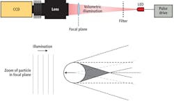
While such stereo techniques allow the velocity of particles to be measured both across and out of the plane, a version of the technique known as Particle Shadow Velocimetry (PSV) uses low-power pulsed light sources to measure the two components of velocity in a plane (see Fig. 2). In this on-axis technique used by companies such as Innovative Scientific Solutions, pulsed LEDs overdriven in a short-pulse mode produce sub-microsecond light pulses. By directing this light through the area to be measured and onto the field of view of a high-speed camera, shadows created by the suspended particles can be recorded. After these images are recorded at two separate intervals, they can be processed using PIV software.
High-speed cameras
In designing PIV systems, a number of high-speed CMOS or CCD cameras can be used. For the integrator wishing to develop such systems, many different cameras are available from vendors such as Integrated Design Tools, Photron, Vision Research, and PCO Imaging. Interestingly, all of the cameras produced by these companies have been used in the past decade by researchers studying PIV.
Before such cameras can be used, they must be accurately synchronized with the laser light pulse to ensure the delay between laser pulses is long enough to capture the displacement of tracer particles and short enough so that particles moving out of plane leave the field of view of the light sheet. After successive images are captured using the PIV technique, the particle vector flow must be computed.
To perform 2-D and stereo analysis of PIV images, system developers and end users can choose from a number of software packages from vendors of high-speed cameras, system developers, third-party software companies, or open source developers. For example, these include the proVISION-XS Windows-based package from Integrated Design Tools, DynamicStudio from Dantec Dynamics, FlowMaster 2D and 3D systems from LaVision, VidPIV from Oxford Lasers, and the OpenPIV software package from Open Source Particle Image Velocimetry.
For those not wishing to build PIV systems from OEM components, companies such as LaVision and Dantec Dynamics offer pre-configured systems that bundle cameras, laser light sources, timing generators, and software.
Holographic PIV
Both on- and off-axis PIV and PSV systems are useful in their ability to provide 2-D and limited volumetric flow, but they do not provide complete 3-D data about fluid flows within a given volume. To accomplish this, a technique known as holographic particle image velocimetry (HPIV) is being explored by researchers.
At the Mechanical and Nuclear Engineering Department of Kansas State University, for example, Hui Meng (now at SUNY Buffalo) developed both in-line and off-axis HPIV systems that can capture the volumetric activity of particle flow. In the design of the off-axis systems, two lasers beams, separated by a short time interval, are separated into a beam that illuminates the 3-D region of the particle field as well as two reference beams (see Fig. 3).
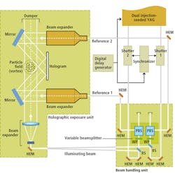
FIGURE 3. At Kansas State University, Hui Meng developed an off-axis holographic PIV system that can capture the volumetric activity of particles. Light from the scattered field then interferes with the reference beams and the interference pattern recorded on the holographic plate.
While the illuminating beam is double-pulsed, the reference beams are alternately single-pulsed, allowing two holographic images to be reconstructed alternately in time. Light from the scattered field interferes with the reference beams and the interference pattern is recorded on a holographic plate.
Today, PIV, PSV, and HPIV techniques are applied in applications varying from analyzing the flow of air over an aircraft wing, to cloud formation, to the motion of insects and fish. Because of the variety of tasks to which these techniques can be applied, nearly every system in use must be custom built.
This—and the cost of the components required—results in prices for systems ranging from upwards of $50,000, a factor that limits their use to universities, research laboratories, and large aerospace and automotive companies (see “Applications of particle image velocimetry” below). Despite this, the results obtained can provide valuable insights into the computational dynamics of fluids and gases.
Acknowledgment
The author would like to thank Mr. Kim Jensen, general manager of Dantec Dynamics, for his help in developing this article.
Applications of particle image velocimetry
Photonic fences zap mosquitoes
As far-fetched as it may sound, Intellectual Ventures has developed a photonic fence designed to rid the enclosed area of mosquitoes. To accomplish this, a series of LEDs mounted on fence posts beam light to adjacent fence posts placed at a distance of 100 ft.
The fence posts are coated with reflective material; light from the fence posts is reflected back toward the light source. By mounting a camera on each fence post, the system can monitor shadows cast by insects as they fly though the vertical plane of light.
The system then trains a nonlethal laser on the insect and estimates the insect’s size, its sex, and how fast its wings are beating. Should the system detect a female mosquito, a more powerful laser is targeted on the insect to kill it.
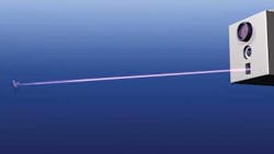
Before building the system, Intellectual Ventures staff needed to analyze the movements of these insects to determine their flight characteristics. To do so, they employed PIV techniques illuminating water droplets using a green planar laser and captured images using a Phantom v12.1 6000-frames/s camera from Vision Research. As the mosquito moves its wings, the illuminated water droplets follow the flow dynamics of the surrounding air, allowing the researchers to visualize the unique signature left by the insect.
For more information on the system, go to http://bit.ly/cIEUrL. To see a demonstration of the system, go to http://bit.ly/do0C7x.
Modeling airflows of an Airbus
During takeoff and landing, powerful vortices are created behind an aircraft. Such vortices result from pressure differences between the upper and lower surfaces of the wing whenever it generates lift. The lift-generating process leads to the formation of a vortex sheet along the trailing edge, which, because of its unstable character, finally rolls up into a single vortex on each side of the wing, forming a pair of counter-rotating vortices.
Such vortices constitute a hazard to following aircraft that may encounter them. This is important during landing when aircraft are flying in trail to approach the same runway. Understanding these vortices and how to control them is the goal of the European C-Wake project.
In the C-Wake research program, a number of experiments were conducted in a small towing tank using an underwater 1:48 scale model of the Airbus A340. The model was submerged to a depth of 1 m and towed at a speed of 3 m/s through the 80-m-long, 5-m-wide tank.
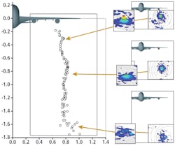
Along the tank, the flow field development over time was measured using a custom-designed PIV measurement system from Dantec Dynamics. As the aircraft model passed the measurement rig, both the camera and light sheet started to move slowly downward to track the vortices in their downward motion.
For more information, go to http://bit.ly/aGziuG.
Understanding woodwind instruments
By shaping the junction between a tone hole and the bore of an instrument, skilled craftsmen can alter the characteristics of a note played using that hole. This so-called undercutting can increase loudness, improve timbre, and change the interval between notes in different playing registers.
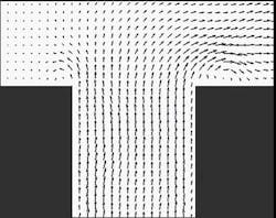
To understand this phenomenon, Rob MacDonald and his colleagues at the University of Edinburgh are using PIV on a simplified clarinet model to visualize the oscillating airflow around a tone hole at millisecond intervals. The formation of jets and vortices has been observed and these phenomena seem to provide the key to understanding undercutting.
For more information, go to http://bit.ly/aLKDRr.
Company Info
Dantec Dynamics, Skovlunde, Denmark
Fastec Imaging, San Diego, CA, USA
Innovative Scientific Solutions, Dayton, OH, USA
Integrated Design Tools, Tallahassee, FL, USA
Intellectual Ventures, Bellevue, WA, USA
Kansas State University, Manhattan, KS, USA
LaVision, Goettingen, Germany
NAC Image Technology, Simi Valley, CA, USA
Open Source Particle Image Velocimetry
Oxford Lasers, Didcot, UK
PCO Imaging, Kelheim, Germany
Photron, San Diego, CA, USA
University of Edinburgh, Edinburgh, UK
Vision Research, Wayne, NJ, USA
Vision Systems Articles Archives