Near-infrared camera monitors selective laser melting process
Conventional parts manufacturing methods such as machining, casting, and forging have existed for centuries, but the process of selective laser melting (SLM) is still in its infancy. “However, where highly complex metal parts must be produced in relatively low volume—for example, in applications such as medical implants,” says Tom Craeghs, a research engineer at the Catholic University of Leuven (Leuven, Belgium), “hybrid solid and lattice designs can be produced in a single pass using SLM.”
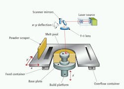
In SLM, a layer of fine metal powder is first coated on a substrate plate onto a build platform that can be controlled in the z-axis. As each layer is applied in the z direction, a laser scanned in the x-y axis is then focused on the 2-D surface to fuse specific parts of the layer together, effectively building a 3-D model.
Creating these 3-D models begins with segmenting 3-D CAD data of the model into 2-D layers of a specific thickness. These data are then used to guide the operation of the SLM process. After the part has been formed, the substrate plate is removed and the part is polished for final customer approval.
To improve the quality of production, Craeghs and his colleagues have developed a vision-based system that reduces problems such as overheating, which can result in an inferior product. “Due to the drastic variations of the border conditions around the laser spot zone, overheating can occur, resulting in large variations in melt pool size,” says Craeghs. “If the melt pool is surrounded by more heat-isolating powder than heat-conducting solid material, the melt pool size increases drastically, deteriorating the part dimensions and the surface quality.”
In addition, during the production process, thin parts may break loose from the building plate. When the metal coater moves over these parts, its blade can be damaged, resulting in the newly deposited layer to become uneven.
To inspect the SLM process as it progresses requires monitoring the length, width, and area of the melt pool in real time and, by using these measurements, adjusting the scan speed of the x-y deflection system and the power of the laser. Because the laser is moving at 1000 mm/s, images from the melt pool need to be recorded and processed at high frame rates.
Reflected light from the melt pool was captured using a 10,000 frame/s CMOS Camera Link camera and transferred to a PXIe-1082 chassis from National Instruments (NI; Austin, TX, USA) using NI’s 1483 Camera Link adapter module interfaced to the FlexRIO field-programmable gate array (FPGA) module (see figure).
As images are captured, they are loaded in the FPGA and thresholded in real time. FPGA software developed by Craeghs and his colleagues is then used to determine a best-fit ellipse of the resulting data, enabling them to determine the length, width, and area of the melt pool. Using trigger lines from the PXI chassis, these data are transferred to the FPGA of an NI R-series I/O-card, which is used to control the laser power and speed of the x-y scanner.
By deploying the system, overheating in the melt pool can be accurately detected and counteracted by diminishing the laser power in real time. A GUI developed in LabVIEW shows the fluctuations in melt pool size over time. In this example, peaks in the melt pool area correspond to overheating that occurred when the laser performed a 180° turnaround. Melt pool vectors can also be stored for further analysis and after the build process is complete, a quality report is generated.
-- By Andrew Wilson, Vision Systems Design
FIGURE: Researchers at the Catholic University of Leuven have developed a system to control selective laser melting (SLM), a process used to fabricate complex parts. In the system, a high-speed CMOS camera is used to monitor the weld pool. Collected data is then used to control and adjust laser power and scanning speed of the system (click image to enlarge detail).