Image compression
By Dave Wilson
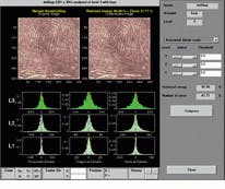
At the US Federal Bureau of Investigation (FBI), more than 30 million sets of fingerprints are stored for cross-reference purposes. When the FBI used Fourier techniques to compress fingerprint images by 20:1, much high-frequency fingerprint ridge information was lost. Now, using wavelet techniques, fingerprint images can be compressed by 20:1 with much less loss of high-frequency information. Thus, the possibility of finding a correlation between new and archived fingerprints is higher (see Fig. 1).
Wavelet methods are powerful tools that enable vision-systems designers to analyze, encode, compress, reconstruct, and model signals and images. Symmetry, scalability, precision, and error tolerance are key advantages of wavelet mathematics that benefit image processing and communications. In addition, with wavelet compression, the silicon required for encoding is virtually the same as required for decoding, rendering the cost of encoding and decoding images equal.
Back to basis functions
Wavelets find their origins in the work of Fourier, who in the 1880s discovered that any signal could be made up by a sum of sine and cosine functions. The transform, which is named after him, has been used for more than a century to represent temporal signals in the frequency domain. However, because the continuous Fourier transform assumes infinite signal length, it cannot approximate small discontinuities, spreading such abrupt bursts over the whole frequency axis.
Like Fourier, mathematicians A. Grossman and S.G. Mallet were interested in describing signals as sums of others. And, in 1984, they recognized that to describe small discontinuous "bursty" signals, it was necessary to use bandpass filters. Narrowing the bandpass filter results in increasing the resolution of the sampled signal. In essence, wavelets are bandpass filters that can be scaled to analyze waveforms at various resolutions, using scale and time as opposed to a frequency representation. But what forms should such bandpass filters take?
There are two types of wavelet transforms--continuous and discrete. Continuous wavelet transforms are used in data-analysis applications in which time-varying signals must be examined. But in signal-processing applications, the discrete wavelet transform reported by Grossman and Malet in 1984 becomes important, primarily because it is computationally simpler.
Mathematically, nearly any function can be used as the basis for a wavelet. And, the mathematicians who per- formed much of this work--Dau bechies, Morlet, and Meyer--have many wavelet functions named after them. But when is the wavelet approach of most use? "The wavelet approach shines when you find a wavelet ("the finite impulse response [FIR] filter") that requires few coefficients (compact support), has good frequency discrimination, and is symmetric (for fixed group delay)," says Kevin Leary of Analog Devices (Norwood, MA). If the wavelet best matches the signal or image, there will be less coefficient data. Such wavelets are useful in image compression because of their data-reduction capabilities.
Unlike Fourier transforms that break a signal down into composite sinusoids, the wavelet transform uses basis functions that comprise irregularly shaped finite-length waveforms. In the wavelet-analysis process, a wavelet itself is compared to sections of the signal to be analyzed.
"The same wavelet is then scaled or moved in time across the signal to be analyzed, and the comparative analysis process is repeated," says Panas Papamichaelis, a senior member of the technical staff at Texas Instruments (Dallas, TX). The result of this process is that a series of coefficients are extracted from the signal.
"If you have a simple transient signal, it might be described by one wavelet," says Papamichaelis. "You then specify how much you need to scale the wavelet to fit the particular transient. In such an instant, the wavelet gives you a compact representation of the transient. But if you have a long-time-length sinusoidal signal, it is better to use the Fourier transform" (see "How Fourier and wavelet techniques compare," p. 54)
There are numerous wavelet families to choose from, including Bior thogonal, Daubechies, Haar, Mexican Hat, Meyer, Morlet, and Symlet. Daubechies wavelets, for example, look like an asymmetrical sawtooth, rather than an upward square wave that is used as the scaling function for Haar wavelets.
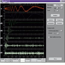
Each wavelet is designed to solve different classes of problems. Figure 2 shows the Symlet function from the Mathworks (Natick, MA) Toolbox, which has been chosen as the optimal solution to perform automatic denoising of a chirp signal. Matching the wavelet to the specific type of signal results in the optimization of the signal-processing operation. The Mathworks Toolbox allows signals to be downloaded and then lets you explore which wavelet provides the desired result on that signal. In many applications, this may depend on how rapidly the signal is changing or how noisy it is.
"There are many categories (families) of wavelets and many wavelets within each category," says Kevin Leary of Analog Devices. "One way to think about all wavelet filters is that they are FIR filters that allow perfect reconstruction of a signal."
Wavelets for compression
In wavelet-based compression, the entire image can be filtered without being broken into sub-blocks, as required in discrete-cosine-transform (DCT) compression. This full-image filtering eliminates the image-degradation effects known as block artifacts of DCT compression and offers more graceful image degradation at high compression ratios.
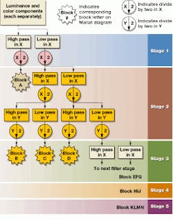
Wavelet image coders can be made by selecting a wavelet representation, a set of quantizers, and an error-free encoding technique. In the first stage, a set of filters and decimators is chosen that operate on the image in horizontal and vertical directions (see Fig. 3).
This results in two different versions of the same portion of the signal corresponding to low and high pass. Usually, either portion is taken and the same operation is performed. The resulting filter tree is known as a Mallat filter tree.
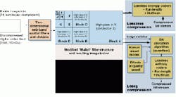
But in the Analog Devices video CODEC, the ADV601, only the low-pass components in the horizontal direction are taken. Hence, the filter tree is known as a modified Mallat filter. This process is repeated until the image has been decomposed to a particular predefined level--in this case 14 spatial frequency sub-bands. The final result is a set of signals that represent the image, but all in different frequency bands. The resultant filtered image is made up of components of the original image (see Fig. 4).
Filters used in the ADV601 apply wavelet basis functions that correlate to the broadband nature of images rather than the sinusoidal waves used in DCT compression schemes (for example, JPEG, MPEG).
Adding quantization
After the image has been filtered, the wave- let coefficients can be compressed with either lossless or nonlossy techniques. To achieve lossless compression, techniques such as run-length encoding, Huffman encoding, or a combination of both can be used. In lossless compression, image data are compressed and can be used to completely reconstruct the image.
To achieve lossy compression, a quantizer determines the number of bits used to allocate to each sub-band. Because the sub-bands are spatial-frequency coded, Leary says, they can be quantized with greater emphasis paid to those frequencies that are sensed by the human visual system, because high spatial frequency is quantized more than low spatial frequency. The statistical distribution of data in the sub-bands is well known for natural images.
In general, the human eye cannot resolve high frequencies in images to the same level of accuracy as lower frequencies. Through intelligent "quantization" of information contained within the filtered image, the ADV601 achieves compression without compromising the visual quality of the image. After quantization, run-length and/or Huffmann techniques can be used to compress the resultant data.
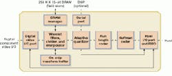
On the ADV601, Analog Devices has implemented a run-length and Huffman encoder on-chip to provide a dedicated solution for video wavelet compression (see Fig. 5 on p. 56). Quadrant International (Malvern, PA) already has announced a PCI-board based on the Analog Devices ADV601 wavelet-compression chip. This board allows developers to store 25 minutes of video on one minute worth of tape. In comparison to other techniques, this provides five times greater compression than other editable compression techniques.
Wavelet technology could benefit varied applications such as medical applications and communications. But it may take time for wavelets to become established in the marketplace, because Fourier techniques are more widely used.
How Fourier and wavelet techniques compare
Signals and images with sharp changes and small or irregular detail are often better analyzed with wavelets than with more-traditional Fourier techniques. With wavelet analysis, the developer can see and explore aspects of data that other techniques may miss, such as trends, breakdown points, discontinuities in higher derivatives, and self-similarity.
So how does the wavelet transform (the basis for wave-let analysis) differ from the Fourier transform? "In some ways it`s very similar," says Ken Karnofsky at The Mathworks (Cambridge, MA), vendors of The Wavelet Toolbox, "in the sense that you take an image and transform it in some way to extract useful information from it."
But the similarities end there. Whereas Fourier analysis consists of breaking down a signal into a sum of sinusoidal components that deliver frequency information, wavelet analysis decomposes the signal into "scale" components. One problem with the Fourier transform, especially when analyzing very wideband signals that extend over a large frequency range, or with nonstationary signals that may vary over time, is that there is always a trade-off between time and frequency resolution. "The Fourier transform assumes that a signal extends infinitely," says Karnofsky.
In reality, few signals are of infinite duration, as Fourier-analysis methods would assume. But if the signals to be analyzed do not specifically meet the Fourier criteria, then the Fourier transform will not be as effective as other methods that might make different assumptions about the nature of the signal.
Other types of Fourier transforms have tried to resolve this discrepancy. Workarounds called short-time Fourier transforms take only a chunk of a signal and analyze that. "Unfortunately, as you shorten the window, you get a finer grain in the time dimension and less resolution in the frequency dimension," says Karnofsky .
The main advantage of using wavelet analysis over Fourier analysis is that wavelets do a better job of resolving the "time-versus-frequency" dilemma. With Fourier analysis, it is a question of one or the other, but not both. "With wavelet analysis, system developers can get good resolution at both high and low scales simultaneously," adds Karnofsky .
Dave Wilson is a science writer in London, England.
FIGURE 1. Wavelet compression techniques have been selected by the FBI for its fingerprint database. Here, an original image (top, right) has been decomposed to three different levels (L3, L2, L1) showing distribution of horizontal, diagonal, and vertical Wavelet coefficients. By disregarding specific Wavelet coefficient values, image-compression systems with little loss of high-frequency (ridge information) can be built.
FIGURE 2.
Using Wavelet transforms, the Chirp signal (S) can be decomposed into different approximations of detail. Having performed such a decomposition, Wavelet coefficients relating to noise can be disregarded and a denoised signal reconstructed.
FIGURE 3. Image filters such as this modified Mallat tree use spatial filters and dividers that operate on the image in horizontal and vertical directions. By repeating the operation highlighted on the resultant data, the tree generates image blocks (in this case 14) that represent different ferquencies in the filtered image shown in.
FIGURE 4. Using wavelet techniques, an image is divided into 14 spatial-frequency subbands per component. At this stage, the filtered image itself takes the form of the modified "Mallet" filter structure shown in Fig. 3. This is then compressed either in a lossy or a lossless fashion.
FIGURE 5. By putting wavelet compression in hardware, Analog Devices` ADV601 is a single-chip CMOS VLSI part capable of supporting 350:1 real-time compression and decompression of CCIR video. The IC features on-chip wavelet filters, quantizer and run-length and Huffman decoders. (b) Quadrant International has developed a PCI-board based around Analog Devices` ADV601 wavelet compression chip that allows 25 minutes of VHS quality video to be stored on 1 min of tape.
