CMOS cameras add frame-grabber functions
Whether the latest generation of CMOS cameras will displace the venerable frame grabber remains to be seen.
By Andrew Wilson, Editor
At many trade shows, the question of whether the “smart camera” will replace current camera/frame-grabber combinations has been debated. While camera vendors tout the benefits of their integrated programmable devices, frame-grabber manufacturers argue for the more-powerful features offered by camera/frame-grabber combinations.
Perhaps the argument, however, is more akin to whether the laptop PC will replace the desktop computer. While each offers certain benefits, it is apparent that desktop PCs have a better price/performance ratio. While the market for consumer laptops and desktop PCs has remained strong, consumer vendors have noticed the emergence of a host of more portable devices ranging from cameras to video and audio devices. In the machine-vision market, this trend is also apparent with camera vendors incrementally adding additional functions to their next generation of cameras.
In part, this additional functionality has resulted from the reduced cost of implementing CMOS sensors, advances in FPGA technology, and the increase in speed of DSPs, CPUs, and media processors. With these advances, it is comparatively easy to design a machine-vision camera, as witnessed by the more than 30 vendors that now offer a variety of CMOS camera types. But while it may be easy to design such cameras, implementing the features required to meet specific machine-vision applications is more complex.
To date, there are more than 10 different analog and digital camera interfaces that integrators can use to build systems. Of these, Camera Link, Gigabit Ethernet (GigE), USB, FireWire, and broadcast analog standards are the most popular among system vendors (see Vision Systems Design, August 2005, p. 53).
Deciding on which digital camera best meets the needs of any specific application requires a thorough analysis of the task to be performed. In the past, frame grabbers were often classed as either “dumb” (those without any processor or memory capability) or “smart” (those with such added functionality). Today’s CMOS cameras fall into similar categories.
There is also some blurring between the specifications of today’s CMOS cameras. For system integrators, however, choosing a CMOS camera depends on the level of performance required. This relies on factors including programmable gain and offset adjustment, global shuttering, variable frame rates, region-of-interest (ROI) monitoring, on-board Bayer conversion, external triggering, on-board programmability, resolution, type of camera interface, and the software support provided.
SHUTTERS AND ROIs
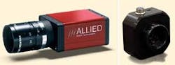
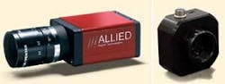
For the developer of machine-vision systems, using a camera with a global shutter is often mandatory, since exposure time and shutter type are critical. In a global shutter, every pixel is exposed simultaneously, resulting in a distortion-free image of a fast-moving object. With a rolling shutter, however, the top row of the sensor is exposed before the bottom row. When the exposure time is reached, the top row is read while other rows are still being exposed. Although all the rows are exposed for the same period of time, the time in which they start and stop exposing are different. Global shutters can be found in many CMOS-based cameras including the 25-frames/s, 1280 × 1024-pixel FireWire Marlin F-131B/C from Allied Vision Technologies and the USB 2.0-based, 27-frames/s, 1280 × 1024-pixel EHDcmos1.3 from EHD (see Fig. 1).
In addition to incorporating global shutters, many CMOS cameras take advantage of the benefits of ROI processing. Because individual ROIs can be addressed in a single camera, it is possible to define specific areas of interest that can be processed by different algorithms. This is especially useful in machine-vision applications where, for example, one ROI could determine whether a part was present and can inspect a specific part of the image. Rather than use a simple trigger to capture an image, the camera itself could determine whether a part was present and then detect any fault in the product itself.
To date, this capability has been demonstrated both by Kamera Werk Dresden and Cognex. At VISION 2004 in Stuttgart, Germany, Kamera Werk introduced its Virtual Camera (see Vision Systems Design, February 2005, p. 16). According to Peter Hoffmeister, Kamera Werk managing director, this allows different regions of the full frame of a single camera to be captured simultaneously and the exposure time, position of the ROIs, and trigger rates of these regions to be independently controlled. In a webcast first broadcast in September 2005, Bill Silver, chief technology officer and vice president of R&D at Cognex, showed how the company’s Checker camera could be used in a similar manner (see “The Most Radical Thing I’ve Ever Done,” at www.cognex.com/Webinars.asp).
HIGH-SPEED IMAGING
While windowing ROIs provides benefits for machine-vision system designers, it also allows CMOS-based cameras to be used in high-speed imaging applications. Although CCD image sensors only allow for a restricted selection of arbitrary windows, this is not the case with CMOS-based cameras. Thus, many manufacturers specify different frame rates at different ROI levels. In the design of its SI-640HF Camera Link-based VGA MegaCamera, for example, Silicon Imaging specifies a frame readout of 250 frames/s at the camera’s full 640 × 480-pixel resolution and 2000 frames/s at 640 × 60-pixel ROI windowed resolution (see Fig. 2).
Given this capability, many manufacturers have developed high-speed cameras using interfaces that include Camera Link, USB 2.0, and FireWire. Because of the amount of data associated with such data rates, Camera Link-based cameras often need little on-board memory to store captured images. In the design of its A504k camera, for example, Basler uses a 1280 × 1024-pixel CMOS imager to achieve 500 frames/s with ROI scanning that allows even higher frame rates.
Other interfaces, such as FireWire, Gigabit Ethernet, and USB 2.0, however, cannot achieve the data rates associates with Camera Link. In these designs, vendors often incorporate on-board memory into their cameras to buffer and store images for transmission over slower interfaces. PCO, for example, has interfaced a 1280 × 1024-pixel × 10-bit CMOS imager with up to 4 Gbytes of onboard RAM. According to PCO, this allows image recording at up to 1 Gbyte/s at speeds of up to 1357 frames/s at VGA resolution. Image data are then transferred over a FireWire interface.
In addition to providing multitasking ROI capability, CMOS cameras are also offloading many image-preprocessing functions from the host framer grabber or CPU. One of the most important of these functions in color image processing is Bayer interpolation. Named after Bryce Bayer, a scientist at Eastman Kodak who patented the concept in 1976, pixels on the image sensor are covered with a mosaic of red, green, and blue transmissive filters. Kodak recently introduced CMOS sensors based on this technology that are primarily targeted toward consumer applications (see “Binning techniques increase signal-to-noise ratio in CMOS imagers,” p. 24).
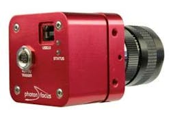
To decode the Bayer pattern, a number of different techniques can be used (see www.cse.iitd.ernet.in/~jvl042439/Vijay_Homepage_Files/ppt1.pdf). Both computationally intensive and repetitive, many of these techniques are ideally performed in an FPGA. Recognizing this fact, companies such as Photon-focus offer cameras that perform this conversion in the camera, offloading the task from the host CPU or frame grabber (see Fig. 3). While the Matrix Vision mvBlueFOX-102 is a 1280 × 1024-pixel USB-based camera that uses a Kodak KAC-9638/48 rolling shutter-based imager, a series of USB-based cameras from Photonfocus is available that incorporate FPGAs to perform Bayer interpolation in real time.
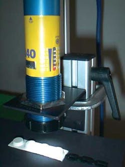
Incorporating FPGAs into CMOS-based cameras can provide other advantages, a fact not unnoticed by companies such as FastVision. In the design of its FastCamera 13 and 40, FPGA-based image compression is used to reduce the data rate, the requirement for high-speed interfaces, and the need for large amounts of solid-state memory. According to FastVision, the company will implement a real-time JPEG-based compression algorithm in a high-speed camera that will allow the developer to use the vastly increased apparent on-board storage capacity or either Camera Link or USB 2.0 interfaces to transfer real-time data to a host PC (see Vision Systems Design, December 2004, p. 44).
MORE POWER
While many CMOS vendors are now incorporating CMOS imagers with FPGAs and onboard memory, others have taken their designs one step further by adding additional processing power in the form of DSPs, CPUs, or media processors. These cameras are currently more expensive than their “dumb” counterparts, but they offer the system integrator a way to develop a complete camera-based solution.
Because these cameras are more complex, system developers must be mindful of the software support provided. Such cameras generally fall into two categories: those based on Pentium or Pentium-like processors and those based on embedded DSPs or multimedia processors. Although the cost of embedded smart camera solutions may be lower, PC-like development tools may not be available with which to develop a machine-vision application. Rather, more specialized development kits must be used to create an application.
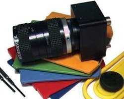
One of the first companies to recognize the power of embedding sensors, FPGAs, and processors into a single camera was Vision Components. The company’s VCM-40, for example, uses a 12-frame/s, 1/3-in. CMOS imager coupled to a 375 MIPS ADSP2185 DSP from Analog Devices (see Fig. 4). Vision Components supplies its own ADSP development real-time operation system and image-processing library.
Cognex also uses an embedded DSP from Analog Devices-the Blackfin processor-in its 128 × 100-pixel Checker product. Unlike Vision Components, however, Cognex has hidden the intricacies of DSP processing behind a user-friendly interface called CheckMate. This allows developers to set up the image sensor, display context sensitive help tips, record, playback, and save images from the Checker sensor.
Fortunately, the move to more friendly embedded-camera solutions has been followed by those touting image-processing software. Although numerous software packages are now PC-based, they can also be run on PC-like smart cameras. In the future, however, it is likely that software vendors will work more closely with hardware developers to reduce the cost of smart cameras.
At this year’s NIWeek (Austin, TX, USA; Aug. 8-10), for example, Glen Anderson, Analog Devices IDDE manager, showed how it was possible to generate C code from LabVIEW, feed this directly to Analog’s compiler, and run the code directly on the Blackfin processor (see p. 47). This represents a rare opportunity for camera developers to provide Blackfin-based cameras that are fully compatible with easy-to-use machine-vision packages. For system integrators, using these cameras will reduce both their development time and the cost of smart-camera-based systems.
Company Info
Allied Vision Technologies
Stadtroda, Germany;
www.alliedvisiontec.com
Analog Devices
Norwood, MA, USA
www.analog.com
Basler
Ahrensburg; Germany;
www.baslerweb.com
Cognex
Natick, MA, USA
www.cognex.com
Dalsa
Waterloo, ON, Canada;
www.dalsa.com
EHD
Damme, Germany;
www.ehd.de
FastVision
Nashua, NH, USA
www.fast-vision-com
Kamera Werk Dresden
Dresden, Germany;
www.kamera-werk-dresden.de
Kodak
Rochester, NY, USA
www.kodak.com
Matrix Vision
Oppenweiler, Germany
www.matrix-vision.com
National Instruments
Austin, TX, USA
www.ni.com
PCO
Kelheim, Germany
www.pco.de
Photonfocus
Lachen, Switzerland
www.photonfocus.com
Silicon Imaging
Troy, NY, USA
www.siliconimaging.com
Vision Components
Ettlingen, Germany
www.vision-components.com