System detects faults in wood-wool slabs
Andrew Wilson, Editor, [email protected]
Fabricated from shredded wool, wood, and a concrete cement binder, wood-wool slabs are mainly used as building material in developing countries. Produced locally in these countries, the material’s low-thermal-conductivity, sound-absorption, and fire-resistance properties makes it a good base for many construction projects.
“After fabrication,” says Christian Madritsch, a senior lecturer at the Carinthia Technical Institute (Villach, Austria; www.ctiac.at), “each 2 × 2-m wood-wool panel must be inspected for rough edges, stains, holes, and surface striping effects. Although these faults do not affect the construction or insulation properties of the slabs, the resulting visual appearance of such defects is unacceptable to building contractors.
In the past, manufacturers such as Herarklt used manual methods to perform this inspection. Unfortunately, the results obtained were often operator-dependent and unreliable. To automate the process of inspecting all three defect types, Madritsch and his colleagues developed a system based on off-the-shelf lighting, cameras, and machine-vision systems. To digitize images of the slabs, a FireWire-based DFB-500 camera from Sony Electronics (Park Ridge, NJ, USA; www.sony.com/videocameras) was interfaced to an NI CVS-1456 Compact Vision System from National Instruments (Austin, TX, USA; www.ni.com).
To illuminate the surface of the slabs, low-cost incandescent lamps were used. “However,” says Madritsch, “to detect whether rough edges were present, the slabs could not be illuminated parallel to the optical axis since any edges in the resulting image would not be highlighted. Instead a 45° off-axis illumination was used. To detect for the presence of rough edges, the green output channel from the CCD camera was isolated due to the high portion of reflected green light from the incandescent lighting. Using this single channel, the brightness and contrast were first increased to increase any edge details.
To find any straight edges of the slabs, Madritsch used the Find Straight Edge (FSE) tool that is part of NI’s Vision Builder AI Configurable Software. Searching over the image from right to left, parameters of the FSE tool are set so that a limit is placed on an allowable number of pixel deviations. Any deviation greater than a specified amount then indicates an unacceptable fault in the wood-wool panel.
To detect stains and holes in the slab, the density of different areas are indirectly measured and compared. To accomplish this, the green output channel is again extracted from the CCD camera. After thresholding, the binary image is inverted and equalized using the lookup tables in the CVS-1456. These operations result in fragmenting the surface of the image into small objects or blobs. Using the count-pixels tool in the Vision Builder AI software allows pixels to be counted in different regions of the image. The output of the pixel-count operation determines the number of stains or holes and statistical analysis determines the level of acceptability of each panel.
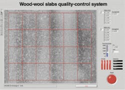
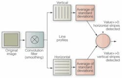
“Because of the way that wood-wool slabs are manufactured,” says Madritsch, “horizontal and vertical striping effects cannot simultaneously occur on any one panel.” As a result, the detection and classification of such effects can be accomplished in two stages. After a convolution is used to reduce the effect of camera noise and any small holes that may appear on the slab, a grid of line profiles is superimposed on the image in both horizontal and vertical directions (see figure).
null
The standard deviation of the line profile pitch is then computed in both the horizontal and vertical directions. Thus, a standard deviation of the line profile perpendicular to stripes will result in a higher standard deviation than a parallel line profile value. Subtracting the horizontal and vertical line profile value results in a value of stripe strength and direction. If this value is greater than zero, the slab has horizontal stripes; if it is less than zero vertical stripes. Smaller values around zero indicate the slab has a uniform appearance.


