Dynamic structured light measures shapes

Algorithm quantifies damage to NASA Shuttle heat-shield tiles.
By C. G. Masi, Contributing Editor
When faced with measuring the shapes of macroscopic objects, most mechanical engineers rely on a coordinate-measuring machine (CMM) that uses a probe-typically shaped like a small sphere-attached to an articulated arm with encoders built into the joints. Either manually or by robotic control, the user brings the ball into contact with the surface of the part to be measured. From the encoder positions, it is straightforward to determine the position of the probe’s center with reference to a 3-D coordinate system. The part’s surface is then known to be tangent to the probe’s surface at some location. By measuring many points, it is possible to resolve the ambiguity and determine the shape of the part.
Coordinate-measuring machines are versatile. They can measure parts having virtually any shape and a range of sizes and can be very accurate. Obtaining high resolution, however, is difficult. Each point must be measured individually, and a large number of closely spaced points must be obtained to determine the shape. Thus, CMM measurements can take quite a long time to complete an accurate model.
Ernest Franke, an institute engineer in the Southwest Research Institute (SwRI) Manufacturing Systems Department, and his coworkers were looking for a more-efficient method for mapping complex parts. “[Ordinary structured light] systems project a fixed pattern, typically a variation of a checkerboard, and determine how the pattern changes on the surface,” says Franke. “They calculate the depth information from triangulation.”
The team did some preliminary work to develop concepts for a dynamic-structured-light (DSL) system, which grew out of earlier government-sponsored work to identify and reverse-engineer various mechanical components. With SwRI support, they developed the concept into a prototype system. So, when NASA needed to quantify Shuttle-tile damage as part of the Shuttle Return to Flight Program, they were ready with a three-dimensional dynamic structured light (DSL 3-D) system.
SYSTEM COMPONENTS
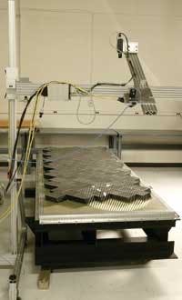
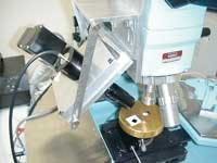
The NASA Shuttle-tile measurement system consists of a projector and a camera mounted on a gantry (see Fig. 1). The gantry holds the projector and camera in place relative to each other and to the object under test (OUT). Actual technical details vary from application to application, depending on the resolution needed and the field of view (FOV) desired. Generally, the angle between the camera and projector optical axes is from 20° to 40° but is usually 30°.
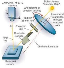
The projector consists of a Dolan-Jenner Fiber-Lite Model 170-D light source, an Edmund Industrial Optics Y56-953 rotating linear grating (or Ronchi ruling), and a Tamron 25-mm projector lens. The light source backlights the ruling, and the lens projects its image onto the OUT.
A high-quality Ronchi ruling consists of a transparent substrate, such as a glass plate, with stripes of opaque material (such as chromium) laid down on it. The stripes are the same width as the spaces between them. The ruling’s quality depends on the straightness and uniformity of the stripes.
The camera is a JAI Pulnix TM-6710 monochrome, progressive-scan CCD camera with a Schneider Optics Xenoplan 17-mm lens selected to include the desired target area in its FOV. It is not necessary to include the entire OUT in the FOV, since it is possible to stitch the results from multiple FOVs together to cover the object.
An electric motor rotates the grating at a constant angular speed about an axis that does not intersect the FOV. It is important that the grating’s rotation axis does not intersect the FOV because the system’s ability to locate the surface point in the third dimension degrades as its distance from the rotation axis shortens, becoming indeterminate at the axis.
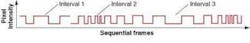
The projection-lens magnification at the surface point and the grating pitch determine the width of the stripes the projector throws onto the surface. As the grating rotates, these stripes pass across the surface, alternately illuminating and shadowing the surface point each pixel sees, producing a train of square waves (see Fig. 2). The waveform consists of square pulses with varying width. The widest pulses occur when the stripes lie at a right angle to the line connecting the surface point to the rotation axis, and the narrowest occur when the stripes lie parallel to that line. The pulsewidth goes through two complete cycles during each grating rotation.
The imaging computer is a Hewlett-Packard workstation xw6000 with dual 3.2-GHz processors, 2 Gbytes of RAM, and a National Instruments PCI-1424 frame grabber. The software was written in ANCI C for portability.
The workstation records each frame from the camera, thresholds it, and updates a pulsewidth waveform for each pixel. It analyzes the pulsewidth waveform for each pixel to identify the grating rotation cycle and count the number of pulses in the cycle. This analysis determines how far the projected grating line observed at each pixel lies from the grating rotation axis.
The rotating grating projection generates a set of quadric surfaces in space. To locate a surface point in three dimensions, the computer has to find the intersection of the ray corresponding to the pixel in question with the identified quadric surface.
The DSL 3-D system has a number of clear advantages:
• It uses inexpensive and readily available COTS optical and vision components
• The geometry can be scaled to any size without changing the algorithms
• It parallel-processes a large number (equal to the number of CCD pixels) of measurements simultaneously, providing a high-resolution map of the OUT surface
• The resulting data can be postprocessed to stitch together large, high-resolution surface-morphology maps and even solid models.
The system was used to measure experimental damage to a panel of NASA Shuttle tiles as part of the ongoing Shuttle Return to Flight Program. Researchers in the Materials Science Test Group of the SwRI Ballistic Laboratories fired pieces of insulating foam at this test panel through a compressed-air cannon.
Assessing damage to NASA Shuttle tiles is not the only use for the DSL 3-D system. Karta Technologies is developing the technology into a commercial product that it will offer to maintenance and repair organizations serving the commercial and military aviation industries (see “DSL inspects aircraft”). For example, the team is developing a system to evaluate microelectromechanical-system (MEMS) devices. They found no problem adapting the system to a standard integrated-circuit probe station microscope. However, many of the MEMS device surfaces are too shiny to easily show the Ronchi-ruling shadows (see Fig. 3).
In another application, Franke’s team has imaged human vertebrae to support a group developing an osteopathic repair technology. “Our biomedical engineering department had a client interested in fusing vertebrae for medical repair of an injury,” team-member Michael Rigney reports. “They needed accurate 3-D models of a couple of vertebrae, which we provided using the DSL system. They imported the models into a CAD design package and used them to demonstrate their repair approach.”