IR lenses maximize detector potential
Specialty optics open the infrared region to demanding vision applications.
By Andrew Wilson, Editor
Although the infrared (IR) camera market continues to be dominated by microbolometer-based cameras, the range of IR cameras now available allows system developers to deploy a variety of sensor technologies to meet applications that may require more-sensitive measurements at specific frequencies (see Vision Systems Design, Oct. 2004, p. 73). In these applications, where high-speed, improved sensitivity or spectral selectivity is required, indium antimonide (InSb), mercury cadmium telluride (MCT), or quantum-well IR photodetector arrays are often used.

For the system integrator, the choice of camera depends on the spectral characteristics of the object or material to be imaged. This can be determined from a plot of transmission vs. wavelength for the specific material. In determining the presence of propane gas, for example, the absorption of IR radiation is dominant at a wavelength of 3.4 µm. Similarly, carbon dioxide can be best imaged in a 4.3-µm transmission band. Using a 5-µm bandpass filter allows the surface temperature of glass bulbs to be measured. For polyethelene film, an overall transmission of 80% or greater is needed to see through the material, while 20% or less is needed to inspect the surface.
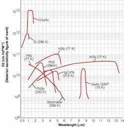
Each detector material exhibits different detector sensitivity across the visible, short-wavelength IR (SWIR), medium-wavelength IR (MWIR), and long-wavelength IR (LWIR) spectrums (see Fig. 1). For the visible region and near-IR (NIR) spectrums, silicon-based CCD and CMOS imagers can be used. Across a wide spectrum, microbolometer-based systems are used in a number of applications, although their sensitivity is much lower than other types of devices. For the SWIR, a number of companies, including Sensors Unlimited and FLIR Systems, Indigo Operations, are using indium gallium arsenide (InGaAs) to enable both visible and NIR imaging on a single IR detector. Electrophysics also produces an MCT-based SWIR system that has a spectral response of 700 nm to 2.5 µm.
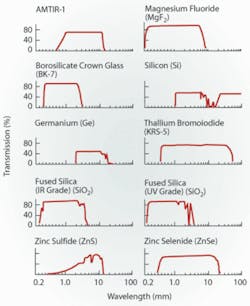
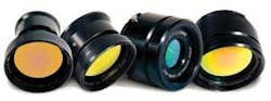
In the visible and NIR regions-from 0.5 to 2.5 µm-camera builders use silica-glass lenses with these detectors because of the material’s high homogeneity and 90% or better transmission in the visible and NIR spectral regions. To match the variety of other detector types currently being produced for imaging in the MWIR and LWIR, more expensive materials must be used. Like the variety of detectors now available, there is also a variety of materials from which these lenses can be produced (see Fig. 2).
ALONG THE WAVELENGTH
“Although there are a variety of materials that can be used to fabricate an IR lens,” says Jonathan Kane, president of Computer Optics, “the most popular materials are amorphous material transmitting IR radiation (AMTIR), germanium (Ge), silicon (Si), zinc selenide (ZnSe), and sapphire.” Each of these materials has its own unique spectral characteristics that must be taken into account when building a lens.
AMTIR, for example, is a glass-like amorphous material with a high homogeneity that transmits in the 0.75-14-µm range. The compound, which is made up of germanium, arsenic, and selenium, is used for IR windows, lenses, and prisms and is not water soluble. “AMTIR-1 is especially useful for lenses built to image IR in the 8-12-µm region, where its absorption and dispersion properties are the lowest,” says Kane.
Because it has the highest refractive index of most IR-transmitting materials, germanium is useful in the design of lenses that might not otherwise be possible. Popular in IR cameras operating in the 3-5- or 8-12-µm regions, germanium blocks UV, visible, and IR to about 2 µm. Thermal runaway is also a problem because the hotter germanium becomes, the more IR absorption increases. This transmission degradation begins at about 100°C, and the material rapidly degrades between 200°C and 300°C. A thorough description of all the properties of materials used to build IR lenses has been developed by Janos Technology.
“In terms of cost,” says Kane, “AMTIR, germanium, and Zerodur are the most expensive of the most popular materials.” Costing about six to seven times as much as silicon and fused silica, each of these materials presents different trade-offs to a lens designer in terms of cost, hardness, water solubility, and heat sensitivity. “In producing a lens with AMTIR, for example,” says Kane, “differential cooling effects at the end of the production process may result in the product breaking.” When using materials such as potassium bromide or potassium chloride, water-soluble polishing compounds cannot be used since they will dissolve the lens.
Infrared lenses are unlike visible lenses. Currently, there are more than 200 different types of glasses that can be used to build a visible-wavelength-based camera. With the large number of choices of glasses available from manufacturers such as Schott Glass, Ohara, and others, more than 100 different lens manufacturers worldwide now supply lenses for visible-wavelength applications. And, because many of these lenses transmit light in the 0.5- to 2.5-µm region, they can also be used in SWIR cameras, drastically reducing the cost of such systems.
Alternative Vision is the US distributor of a range of IR lenses from Optec. According to David Gilblom, president of Alternative Vision, these are offered with focal lengths from 25 to 300 mm and can cover either the 900-1700- or 1700-3000-nm spectrum with the appropriate antireflection coatings. Primarily used with InGaAs imagers, the lenses are available with Canon bayonet- or C-mounts.
MEDIUM AND LONG WAVELENGTHS
For MWIR and LWIR cameras, the choices of lens materials are far narrower. “In the MWIR,” says Kane, “germanium and silicon are generally the materials of choice, while in the LWIR, AMTIR and germanium are used. Because of the cost of these materials, the resulting price of lenses for LWIR is higher than that for both MWIR and SWIR, with SWIR lenses being the least expensive.” For the MWIR and LWIR spectrum, major lens suppliers include Janos Technology, Ophir Optronics, Diversified Optical Products, and Telic Optics (both of the latter have been acquired by Axsys Technologies).
Specifying a lens for SWIR-based systems is relatively easy since standard C-mount lenses are typically used. “However,” says Chris Alicandro, director of sales at Electrophysics, “no such standards exist for MWIR and LWIR. One cannot simply ask a lens supplier for a C-, F-, or bayonet-mount lens. It is more complicated.”
Computer Optics’ Kane explains, “In a visible lens, there are a number of glass elements and an aperture stop in the center.” In MWIR and LWIR lens designs, placing a stop in the center of the lens would result in unacceptable heating of the stop. “This is why in cooled IR camera systems, the stop is placed behind the lens. This distance to stop and camera can be used to determine whether a specific lens can be mounted on an IR camera. This is unlike a C-mount lens where the C-mount standard defines the back focus-the distance from the last optical surface of the lens to the focal plane of the camera.”
REIMAGING LENS
Many lens designs are used with IR focal-plane-array systems. For example, there are both reimaging and nonreimaging lenses. “In a reimaging lens, there are intermediary and primary image planes and a field stop,” say Electrophysics’ Alicandro. “Holistically, this is a great design for certain types of measurement systems. Nonreimaging lenses do not have an intermediary focal plane. Typically these lenses are perfectly suited for most imaging applications, but, unless they are designed properly, they may adversely affect performance in radiometric applications.”
In a reimaging lens system, the image being viewed is in focus at two points in the optical path-one at the detector and one in the middle of the lens at an intermediate image plane. At the intermediate image plane, a field stop is placed in the optical path to block the energy due to objects outside of the normal field of view. Without this capability, imaging and measurement data can be corrupted with the radiation from extremely hot objects that reside outside the field of view.
Often, systems with reimaging lenses are used in industrial environments in which there are a variety of hot and cold objects around the object being measured. Systems without this lens design can result in measurement errors as a result of off-axis stray energy falling on the focal-plane-array detector.
In contrast, in a nonreimaging lens, the IR image is focused at only one point-the focal-plane-array detector-and the lens design may not have a way to adequately absorb intense off-axis stray radiation. These lenses are widely used in camera systems where the effects of high-intensity stray radiation on measurement accuracy is of little concern. Such lenses are also smaller and lighter than re-imaging lenses, since they have fewer elements and are less expensive to manufacture than reimaging lenses. However, when using this type of lens system for accurate measurements, users should be aware that external sources of IR energy can change the resulting image and measurement data.
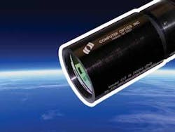
This concept is embedded in a number of IR zoom lenses currently available from Computer Optics. Designed for SWIR, MWIR, and LWIR applications, the lenses all feature a 4X zoom capability and have been especially tailored for InGaAs, InSb, and microbolometer-based detectors (see Fig. 3). Computer Optics SWIR, MWIR, and LWIR lenses all feature a variable focal length between 50 and 200 mm. Operating across the 3-5- and 8-11-µm spectrum, respectively, the MWIR and LWIR lenses are especially suited for use with InSb and microbolometer devices.
“In the design of any lens for IR applications,” says Kane, “it is important to match the spectrum of the detector device with the material of the lens.” In many of today’s IR applications, specific frequencies from 0.9 to 1.7, 3 to 5, 8 to 10, and 8 to 14 µm are generally used.
“Similarly,” says Alicandro, “the f-number (or aperture) of an IR system is determined by the inherent sensitivity of the detector.” A high-quantum-efficiency detector (for example, InSb or MCT) is so sensitive that it does not need an extremely fast lens design. That is why there typically are no MCT or InSb IR cameras with lenses faster than f/2.0. In fact, some of these systems are supplied with f/4.0 lenses. However, if a very-low-sensitivity IR sensor, such as a microbolometer or a BST sensor is used, then a very fast lens is needed.
A microbolometer with an f/2.9 design, for example, would result in a noise-equivalent-differential temperature of about 500 mK (or worse) because the sensor would be starved of energy. “This is why microbolometer-based cameras usually have f/1.0 designs and why their depth of field/focus is poor,” Alicandro says.
CHROMATIC ABERRATION
Chromatic aberration occurs when different wavelengths of light are not all focused at the same point. This occurs in IR systems because these systems typically sense energy over a range of wavelengths. In LWIR systems, for example, wavelengths between 8 and 14 µm must be detected. Without correction, energy at 9 µm may be focused and energy at 10 µm might be fuzzy, resulting in an image that is not sharp and that would give measurement errors. To compensate for this, lens manufacturers have developed “color-corrected lenses” that use several optical elements that in the visible are known as crowns and flints.
“In the design of an optical lens,” says Kane, “only light across the 0.4-0.7-µm spectrum needs to be captured.” In the LWIR, the spectrum is between 8 and 14 µm, and the wavelength difference that must be detected is an order of magnitude higher than that of visible light.” In these systems, chromatically corrected lenses focus the range of wavelengths to a single point using different types of optics often made from different materials. Although the design of the lenses may at first appear more complicated than the design of optical-based systems, the relatively large pixel pitch (of approximately 25 µm) of IR sensors allows a broad range of wavelengths to be captured with IR lenses.
Company Info
Alternative Vision,
Los Altos, CA, USA
www.alt-vision.com
Axsys Technologies,
Rocky Hill, CT, USA
www.axsys.com
Computer Optics,
Hudson, NH, USA
www.computeroptics.com
Diversified Optical Products,
Salem, NH, USA
www.diop.com
Electrophysics,
Fairfield, NJ, USA
www.electrophysics.com
FLIR Systems, Indigo Operations,
Goleta, CA, USA
www.indigosystems.com
Janos Technology,
Townshend, VT, USA
www.janostech.com
Ohara,
Hofheim, Germany
www.ohara-gmbh.com
Ophir Optics,
Wilmington, MA, USA
www.ophiropt.com
Optec,
Milan, Italy
www.optec-spa.com
Schott Glass,
Elmsford, NY, USA
www.us.schott.com
Sensors Unlimited,
Princeton, NJ, USA
www.sensorsinc.com
Telic Optics,
North Billerica, USA
www.telic.com