Choosing an optical filter for vision
Understanding how and when to use filters can save time and money.
By Jason Dougherty
Developers of machine-vision applications know that considerable emphasis has been placed on choosing the correct lighting to achieve maximum contrast. While correct lighting can overcome many imaging problems, the wrong lighting can cause even the most sophisticated system to run too slowly or give an excessive number of false rejects or false accepts.
When compared to lighting hardware, little is understood about the use of filters in machine-vision applications. Relative to most lighting equipment, filters are less expensive, easier to obtain, and, in many cases, can significantly improve results. Unfortunately, knowing which filter to select, which options are readily available, and where to get them can be a problem. Despite this, a variety of off-the-shelf filters are available from a number of vendors, and this low-cost investment can result in very large returns. In many cases, when faced with developing a machine-vision system that has a lighting problem, it makes sense to examine the benefits of optical filters before ordering lighting hardware.
Color and contrast
Testing different colors of LED lighting can be cumbersome, expensive, and time-consuming. To understand whether a proposed color is a good choice, placing a filter in front of the camera lens provides a quick way to determine if a desired effect will occur. Testing can involve the use of a single filter or combination of filters that may serve more than one function. Those who are not sure what effect different colors may have should consider acquiring a swatchbook, a filter kit, or a variety of filters to use as a tool. To understand what these filters are doing, it is important that spectral data or transmission curves be supplied with them.
In color applications, complementary colors form the most dynamic contrasts. The same is true when monochrome cameras are used, except that when using color filters, results are seen in black, white, and varying shades of gray. In such cases, the optimum contrast between two subjects provides a very white white and a very black black within the same scene. This is done by maximizing the amount of light transmitted in at least one wavelength range and minimizing the amount transmitted (or attenuated) in another range. For example, to brighten or highlight a subject that is predominantly blue, transmission in the blue portion of the spectrum must be maximized and much of the green, yellow, red, and other portions of the spectrum blocked.
“Color” filters attenuate light within some portion of the visible spectrum and have an obvious color. Such filters can be categorized as short-pass, long-pass, and bandpass filters.
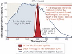
Short-pass filters pass shorter wavelengths of light while blocking longer wavelengths. Long-pass filters do the opposite, passing longer wavelengths and blocking shorter wavelengths. These filters are usually identified by their 50% points. This point can be thought of as the point at which 50% of the light is being transmitted and 50% is being blocked-a halfway point in the transition from blocking to transmitting, or vice versa. So a red 630-nm long-pass filter, for example a Midwest LP630, might be well suited to applications using 660-nm LED or structured laser-diode lighting. It blocks lower-wavelength light, has a 50% point at 630 nm, and has very high transmission at 660 nm and beyond. However, this LP630 long-pass filter would not be suitable for use with 630-nm LEDs.
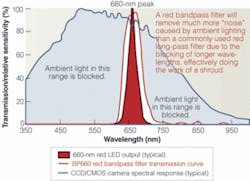
To achieve maximum contrast in this 660-LED lighting example, 100% transmission at 660 nm is desirable, while most of the ambient light should be completely blocked, with as sharp of a cut-on and cut-off as possible. While to the human eye the LP630 may appear a good filter choice, most CCD/CMOS cameras have excellent near-infrared (NIR) sensitivity, and considerable near-UV sensitivity, as well. Many of these cameras have sensitivity that peaks in the NIR. When a graphic representation of a typical CCD/CMOS spectral response curve is superimposed on the filter’s transmission curve, it is clear that the LP630 does not block as much of the light to the camera as one might imagine (see Fig. 1). Perhaps slightly more than half of the extraneous light that the camera is sensitive to is being blocked. For this reason, my company recommends the use of a broad bandpass filter for these applications, such as the BP660 filter (see Fig. 2)
null
A bandpass filter is named according to the central or peak wavelength that it transmits and will block longerand shorter wavelengths, resulting in improved contrast and better control over changes that may occur over time in ambient lighting conditions. In the case of bandpass filters, “broad” is necessary in most machine-vision applications because this allows for variations in the spectral characteristics of the LEDs or laser diodes. For example, most 660-nm LEDs will have at least a ±10-nm tolerance assigned to their peak wavelength. The filter chosen must perform well over this entire range. A broad bandpass also allows a filter to perform well when wide-angle or shallow-incident angle lighting is used.
Polarizing filters
Light reflected from a nonmetallic surface, such as glass, lacquer, plastic, or liquid, results in polarization of the reflected light. This polarized reflected light can be the result of uncontrolled ambient light, but is more often from the light source chosen for illumination. As the angle of incidence of the light and the camera relative to the subject are about the same and approach 55° to normal, a “glare” and loss of contrast become more pronounced.
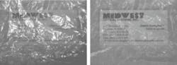
In situations where the subject is partially obscured by this unwanted reflection, using a polarizing filter can reduce or eliminate the problem (see Fig. 3). Polarizing filters can also highlight stress patterns in clear plastic or glass to determine whether glass has been properly tempered.
Many polarizing filters consist of a plastic film-a very fine, “Venetian blind” grid, laminated between two pieces of glass. This grid is invisible to the eye and the camera’s sensor, is generally gray in color, and allows visible light in only one polarization plane to pass through. By rotating the filter mounted on the lens, highly polarized “glare” can be decreased. Further reduction is possible by polarizing the light source. Polarizing plastic sheet material from 0.005 to 0.030 in. thick can be easily cut to desired shapes and sizes to cover the light source.
Neutral-density filters
In conditions where lighting is extremely bright, neutral-density filters can be essential. They generally appear gray in color and reduce the amount of light reaching the sensor without affecting color balance or contrast. Such “stock” filters can range from an optical density (OD) of 0.30, which transmits about 50% of visible light, to OD 1.20, which transmits about 6.25% of visible light. In addition, polarizing filters can also function as neutral-density filters with an OD of 0.50, transmitting about 32% of available light.
By standardizing part numbers based on OD, densities are additive when combining two or more filters. In these situations, an “OD” scale is more convenient than using a “% transmission” scale. For example, a ND030 filter (OD = 0.30) used with a ND090 filter (OD = 0.90) would result in a combined OD of 1.20. Similarly, using two ND060 filters together would produce the same result.
In machine-vision applications, another common use for neutral-density filters is to decrease the depth of field by allowing wider lens apertures to be used. This helps to separate subjects from their foreground and/or background, as the subject will appear in focus, while the background will be out of focus. In situations involving very bright ambient light, or when cameras must be directed at high-intensity beams such as automotive headlamps, neutral-density filters reduce the amount of light captured by the CCD/CMOS imager.
IR and UV filters
Working in the NIR or UV portions of the spectrum offers significant advantages. Contrast in the NIR can be greatly improved depending on the characteristics of the item under inspection. Perhaps 50% of the information captured in NIR images is significantly different when compared to those images captured with white light. This “50% rule” can apply to any given type of subject. However, without prior knowledge it is often impossible to tell how an image will appear in the NIR without experimentation. Fortunately, most CCD and CMOS cameras have excellent near-IR sensitivity, so such tests can be performed quickly and easily by slipping a visible-blocking/IR pass filter over the camera lens. When a difference does appear, these filters can provide the optimum separation between subject and background (see Fig. 4).
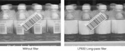
When working in the IR, the camera’s spectral response must be understood and the lighting and filtering properly matched. For example, one would not use 940-nm LEDs if the camera’s response were close to zero at 940 nm. Today the most commonly used IR LED wavelength is 880 nm, and, for most cameras, spectral response beyond 880 nm drops off rapidly. This is true even for those cameras that advertise excellent NIR sensitivity, although their response at 880 nm can be two-to-three times greater than that of a standard CCD. For this reason, an IR bandpass filter is normally not recommended. A long-pass IR filter for blocking shorter wavelengths, such as an 830-nm long-pass filter, should be used. In a sense, the camera itself filters longer wavelengths. Using a bandpass filter would result in increased cost and/or some reduction in peak transmission.
In what are usually referred to as UV applications, 99% of inspections are not performed in the UV. These applications use UV or shorter-wavelength lighting to excite a part or material under inspection. This material then emits light, usually somewhere in the visible portion of the spectrum. Often this fluorescence can be weak and difficult to image. For such applications, a visible bandpass filter that is appropriate for the emission wavelength is recommended. This bandpass filter should provide maximum transmission over the given wavelength range and block as much of the rest of the ambient light as possible-particularly the UV portion of the spectrum being emitted by the light source. With the use of CMOS cameras becoming widespread, a larger number of cameras now seem to have significant UV sensitivity.
It is also very important to select UV lighting that matches the luminescent material. Selecting 390-nm LED lighting may seem to make economic sense, but if the material’s excitation wavelength is at 365 nm, this can be a poor choice. Under even optimal conditions, fluorescence can be extremely weak and difficult to detect if the wrong LED lighting is selected.
Jason Doughertyis sales engineer at Midwest Optical Systems, Palatine IL, USA; www.midwestopticalsystems.com.