Three-camera system with optical filters and telecentric lenses checks electronic connectors.
By Claudio Sedazzari and Francesco Monguzzi
As production standards become stricter to comply with international norms, vision systems are being used more frequently in electronic-connector inspection and dimensional measurement. The shape, material, and small dimensions of connectors dictate that optical inspection is the best way to inspect the parts for small damages and defects and is the only method that can achieve precise, repeatable, fast dimensional control on a production line.
With traditional mechanical instrumentation such as contact gauging, it is nearly impossible to measure all of the features of such small parts-for example, the distance between two object points, an inner hole diameter, concentricity, curvature radii, angles, and intersections between two sides. In addition, the demands for accuracy are very high because every dimensional specification must be met by 100% of connectors to ensure male-to-female compatibility, electric contact, and the absence of contact losses.
On-line system
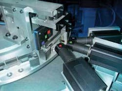
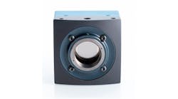
To help ensure the quality of these electric and electronic-connector components, a machine-vision system was needed that could make noncontact measurements of all the relevant dimensions of precisely turned cylindrical pins made of polished metal with varying shapes. To obtain the maximum measurement accuracy-in the range of ±2 µm-it was necessary to take images of small object areas. To do this, each piece was imaged by three different cameras looking at three different object regions. The first camera looks at the top of the pin, the second at the middle, and the third at the bottom. Industrial cameras with 1/2-in. detectors and megapixel resolution were used (see Fig. 1).
To keep the magnification at a good level, a 1/2-in. CCD detector was chosen instead of a 2/3-in. detector to preserve the optimal depth of focus necessary to look at objects of different diameters and to take into account nominal position deviation caused by part-placement tolerances. Because of the reduced part dimensions, it was not possible to place the three cameras one over the other, aligned on the same axis. A 30° displacement of the three viewing points was necessary.
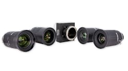
Each camera was equipped with an Opto Engineering telecentric lens. A telecentric lens was required for this application because low distortion and good field depth are necessary, but the most important advantage was the ability to make precise measurement even when the part was not in its nominal position. The adoption of telecentric lenses has nearly tripled the system accuracy, compared to the accuracy achieved in the prototype stage of this application, which initially employed standard entocentric lenses.
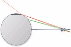
Accurately measuring a polished cylindrical metal part can be very difficult because this kind of object reflects light coming from the sides and, therefore, the diameter appears to be much smaller than it actually is because the cylinder sides seem to be as bright as the background (see Fig. 2). To overcome this, the typical method is to use a collimated source or reduce the area of the backlight illuminator. In our application, a collimated source could not be used because of mechanical constraints, while a reduction of the backlight area was not possible because the object was observed from three different viewpoints.
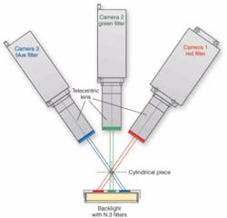
To eliminate the border effects caused by a large backlight, each lens was mounted with a different bandpass optical filter (red, green, and blue), and the backlighting area was also divided into three regions, each covered by the same kind of interferential filter mounted on the lens pointing to that illuminator zone. In this situation, each camera is reached only by the light coming from the corresponding area on the backlight, and no light is reflected on the cylinder edges of the telecentric lens from surrounding areas (see Fig. 3).
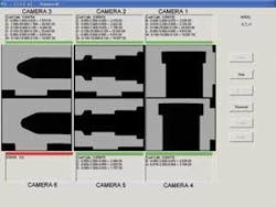
Each image captured by the cameras was analyzed and every dimension was checked at subpixel resolution. The tracing of measurement lines on the image took in account the inclination of the part with reference to x and y axes. To tune the dimensional scale, in each image a calibration reference with known dimensions was placed on the side of the object to be able to define the exact pixel-to-millimeter conversion. These calibration references also made possible the correlation among the measures of each image, allowing the determination of the overall dimensions (see Fig. 4).
Each production line is equipped with two complete systems, each with three cameras, allowing the simultaneous control of two pieces. The six cameras are connected to the same PC with a Gigabit Ethernet interface and grab an image simultaneously following the same trigger signal. This makes possible a faster acquisition with no synchronization problems. Each frame coming from each single camera is analyzed to ensure the measurements are within the defined mechanical tolerances for part acceptance. The PC can also send a signal to a PLC to trigger the management of the defective pieces, which must be taken off the production line. The control rate reaches 120 pieces/minute, taking into account the movement mechanism.
The system operator sees six images and corresponding measurement results, which are displayed as green and red flags for parts within or out of the specified tolerances.
Off-Line System
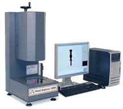
Besides calibrating overall measurements of the on-line system, an off-line system controls the on-line system accuracy, defines the shape model of parts, and makes a crosscheck control on 1% of production. This system is also equipped with a megapixel camera. The part is positioned above an antireflection-coated glass plate with a red LED side-injection backlight behind it. To reduce border effects, the area of the backlight can be windowed by two sliding black sheets, partially covering the emitting surface of the illuminator (see Fig. 5).
A TC 23 64 Opto Engineering telecentric lens is placed above the part, with the alignment of the optical axis perfectly orthogonal to the glass plate to achieve the best performance. The measurement is compared with the theoretical shape model parameters stored in a database.
It is also possible to change the telecentric lens to resize the imaged object area and tune the resolution. After calibrating the system with a geometric pattern and a calibration software tool, the system can control, with the desired geometrical accuracy, objects ranging from 2 to 144 mm.
CLAUDIO SEDAZZARI is CEO of Opto Engineering, Mantova, Italy; www.opto-engineering.com. FRANCESCO MONGUZZI is CEO of Itec Vision, Milan, Italy; www.itec-vision.it.
null
