Graphical environment supports branching, looping
Andrew Wilson, Editor, [email protected]
Many system integrators use graphical programming languages to prototype or develop machine-vision software (seeVision Systems Design, June 2006, p. 29). Using these packages, developers can rapidly build systems with graphical icons that represent the functions of a variety of image-acquisition, processing, and display functions.
One package, Vision Builder for Automated Inspection (AI) from National Instruments (NI; Austin, TX, USA; www.ni.com), is a configurable machine-vision development environment that includes NI’s Vision Acquisition software, a set of drivers and utilities that acquire, display, and save images from any NI frame grabber, IEEE 1394 camera, or GigE Vision camera.
“Configurable vision software typically uses a linear sequence of events to process images.” says Nicholas Vazquez, a principal software engineer in the NI Vision R&D Group. “Often, however, it is necessary to process images in a nonsequential fashion. For instance, should an inspection be required that is based on previous characteristics found by the machine-vision system, a branching mechanism is needed to perform the task. Similarly, after locating and counting objects within an image, it is often necessary to inspect their individual features. Although such tasks can be performed linearly, they are best performed using looping operations.
“To perform branching and looping functions within Vision Builder AI,” explains Vazquez, “an integrated graphical state machine was incorporated into the software.” Each state includes a set of inspection steps that are executed sequentially. These inspection steps can be built from any of the more than 50 tools in the Vision Builder AI graphical software library. Transitions between individual states are then evaluated using effectively graphical “if/then/else” like models to determine the next state.

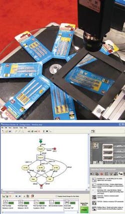
To demonstrate these capabilities at this year’s NIWeek, an image from a FireWire camera was used to digitize a number of packs of Bosch U shank Jigsaw blades into NI’s Compact Vision System (CVS; see figure). The blades are offered in a number of configurations including 14-, 20-, and 24-teeth-per-inch (TPI) variations. After images are acquired by the CVS, each of the packs is inspected to determine the type of blades that should be present in each of the packs.
To carry out this inspection, optical character recognition is performed in the “Inspect” state of the graphical state machine. This identifies the type of pack that is present and whether 14-, 20-, or 24-TPI blades should be present. Depending on the result of this step, three different tasks then check for the presence, correct placement, or absence of a specific part within each pack. This is done using the three state machines-14 TPI, 20 TPI, or 24 TPI-that follow the initial inspection.
After performing each task, the system can then determine whether a specific pack of jigsaw blades should be accepted or rejected. As can be seen, every state within the system has a default transition state that is always true. Should the initial inspection or any of the subsequent inspections fail, then the part will be immediately be rejected.
While effectively demonstrating the use of branching within a state machine, some machine-vision inspection tasks require that the same algorithm be repeated on a number of objects within an image. Accommodating these tasks requires first acquiring and locating these objects and then iterating an inspection operation a number of times over these objects.
“Using Vision Builder AI 3.0,” says Vazquez, “the developer can set the number of iterations within a specific inspection state using a global variable.” Unlike many other development environments, Vision Builder AI 3.0 has been designed for those developing machine vision systems, rather than just machine vision software. By incorporating an NI IMAQ I/O step that supports the company’s Compact Vision Systems and frame grabbers, the developer can, for example, read and write values and measurements to and from TTL and optoisolated digital lines and detect input line changes.
For added analog I/O and digital port control, an NI DAQmx I/O step supports a number of NI data-acquisition devices. By incorporating industrial I/O steps, handshaking can be neatly incorporated within a Vision Builder 3.0 state machine to automatically control, for example, a programmable logic controller.
Finally, NI has also added a number of image-processing functions to the Vision Builder AI package. These include optical character verification, data matrix code grading, and local adaptive thresholding.