Machine vision checks catalytic converters
Multiple cameras on a production line speed the inspection of catalytic converters.
By Andrew Wilson, Editor
Automobiles use catalytic converters to reduce carbon monoxide, nitrogen oxides, and the hydrocarbons that are produced as a result of fuel combustion and evaporated unburned fuel, thus reducing air pollution. Generally, the converters consist of a ceramic or metal structure coated with a platinum catalyst. To minimize the expensive catalyst components while maximizing the surface area of the converter to the engine exhaust, the converters use a honeycomb structure.
“In the construction of converters,” says Brian Smithgall,” president of Image Labs International, “manufacturers use ceramic extruding systems or (less frequently) metal-forming processes to generate honeycomb structures.” After formation, these structures have their inner channels coated with a catalyst material before they are canned for deployment on an automobile.
“During the extrusion and forming process,” says Smithgall, “a number of different defects can occur. These include plugs within the honeycomb structure, edge chips, cracks, and bad end-cuts. Metal-formed converters can also exhibit a number of defects that include separated or crushed foil or double layers.” Defects in the final product may result in insufficient exhaust flow or incomplete cleaning of the exhaust.
After inspection, a coating process covers the cell walls with a thin layer of compounds containing the chemical catalyst. After coating, each product must be checked for the proper coating thickness and uniformity and to see whether any chips and gouges have been introduced. After this process is complete, the coated product can be canned. This is often followed by an inspection step that checks the final dimensions of the part and whether the correct part code is in place.
Inspection steps
Says Smithgall, “A number of inspection steps must be performed.” Rather than develop a separate inspection station for each step, however, Smithgall and his colleagues at Image Labs have developed a single inspection station that checks for every fault at each stage of the manufacturing process.

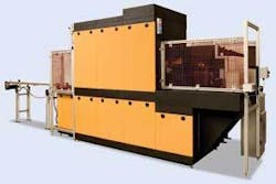
“Because customer requirements may vary,” says Smithgall, “the CatPro system has been built in a modular fashion (see Fig. 1). In this way, should a customer wish to examine only the converter for blocked cells within the structure of the converter, for example, the system can be configured for just that purpose. Often, however, a manufacturer may wish to examine the part after it has been extruded and then again after it has been coated. The same system can be configured to perform multiple functions.”
In a fully configured system, the defects on each catalytic converter are inspected at five different stages (see Fig. 2). To inspect for any plugs that may be present, the part is first back-illuminated using a DCR IV halogen light source from Schott North America that is coupled to an area fiberoptic backlight, also from Schott.
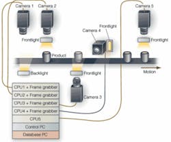
According to Smithgall, the white acrylic diffuser plate used in the backlight provides the optimum combination of light uniformity and intensity with which to image light transmission through the part. As light is transmitted through the honeycomb structure of the part, any plugs that may have occurred during manufacture will block the light.
“Because we needed to achieve a resolution of approximately 0.004 in. on the surface of the part,” says Smithgall, “a 2k × 1 linescan Camera Link camera from Basler, coupled with a fixed-focus Rodagon lens from Rodenstock, was used to capture high-resolution images as the part moves across the camera’s field of view.” The images are then transferred to a host-based industrial PC equipped with an X64-CL Camera Link frame grabber from DALSA. “It takes approximately 1 s to acquire the image as the part passes through the system,” says Smithgall, “after which the image is processed on the host PC while the next image is acquired.”
After back-illumination checks for plugs within the converter, the part passes to a second station. Here, the uniformity of the honeycomb cells on the surface of the part is inspected to check whether any layers have been crushed in the manufacturing process. To obtain a sharp, high-resolution image of the part, the surface of each part is illuminated using two DCR IV halogen light sources from Schott interfaced to two custom linear light lines, also from Schott. By mounting these at an angle, linear light lines focus light energy at the same point on the surface of the part while allowing a DALSA 8k x 1 Camera Link camera to be focused though the light lines directly on the illuminated surface.
“By using an 8k × 1 linescan camera,” says Smithgall, “the system can resolve a distance of approximately 0.001 in. of the surface of the part. As the part moves along the conveyor, surface images of the part are again captured and transferred to the PC using another DALSA X64-CL Camera Link frame grabber.
“Since both sides of the catalytic converter must be inspected,” explains Smithgall, “a similar setup is used in the third stage of the inspection process.” By mounting the camera under the part being conveyed, a third lighting and camera system is used to capture the underside surface of the converter. Images from the 8k × 1 linescan CCD camera used in this stage are captured by another X64-CL frame grabber also housed in the industrial PC.
Cracks and dents
Once the part has been checked for the presence or absence of plugs and the integrity of the honeycomb cells, the surface of the part must be inspected to check for any cracks, nicks, or dents. “Since the surface of each part must be inspected,” says Smithgall, “the fourth inspection stage lifts and rotates the part so that its outer surface can be imaged by a linescan camera.” The part may not be cylindrical; many catalytic converters now being manufactured are round, oblong, or of asymmetrical form.
To properly image the surface of these parts, Image Labs once again used a Schott halogen light source coupled to two line lights. Instead of mounting this illumination system at the top of the part, it is used to image its surface as it is rotated (see Fig. 3). To do this, a DALSA linescan 4K x 1 Camera Link camera was fitted with a Rodenstock Rodagon lens.
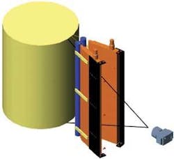
“Because the light generated by the illumination system is very intense, the lens could be stopped down to achieve a large depth of field. In this way, the surface of asymmetrical parts can be captured and transferred to the host CPU using another X64-CL frame grabber. Captured images are then processed and analyzed for any cracks or other surface defects. “At the same time,” says Smithgall, “any Data Matrix code that the manufacturer has printed on the outer surface of the part can be read.”
The system can immediately document any defective batches, the time, date, make, and model of the part, and where it was manufactured. “Such data are very useful for manufacturers,” says Smithgall, “since the information allows the manufacturer to track any faults and confirm trends that may be occurring in the manufacturing process.”
Final inspection
After the surface of each part is analyzed, the final inspection stage checks any label that may have been placed on the top part. An amber LED ringlight from Image Labs illuminates the part. Images of the surface of the converter are then captured by a 1.3-Mpixel FireWire area camera from Allied Vision Technologies equipped with a lens from Fujinon. This camera was interfaced to the industrial PC using the FireWire interface.
“In its full configuration,” says Smithgall, “the CatPro system can inspect more than 30 different types of defects.” To perform these imaging tasks, Image Labs used the Common Vision Blox (CVB) Foundation Package from Stemmer Imaging. “Typically,” says Smithgall, “a number of different cameras and drivers must be supported in the CatPro system. Using the CVB Image Manager, the frame grabber or camera can easily be changed without rewriting any software. More than 30 CVB software tools such as edge detection, segmentation, shape matching, defect detection, measurement, and classification are used to perform specific imaging functions in the system.”
Modular software
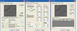
One particular function performed at stage two and three of the inspection process checks the uniformity of the honeycomb cells on the surface of the part. To do this, a number of CVB tools are linked together in a Visual C++ environment (see Fig. 4). After images are captured, they are binarized and thresholded. Image segmentation then classifies regions within the honeycomb structure.
The CatPro’s modular design means that it can be rapidly reconfigured to meet the differing needs of multiple manufacturers. Some companies, for example, may wish to inspect only a statistical sample of converters for any plugs that have occurred. To accommodate these customers, Image Labs has developed a stand-alone version of the system in which parts are manually placed over a light table and imaged from above. To inspect both sides of the part, the operator must manually turn the part over.
“In other situations,” says Smithgall, “automatic systems may be required to inspect every part.” Some manufacturers, however, may not wish to test for any final assembly parameters such as correct label placement. By engineering the CatPro in a modular fashion, the system can be scaled as required,” he says.

null