3-D vision system checks tires
Difficult-to-image black-on-black characters can be easily recognized as a result of laser-based imaging.
By Andrew Wilson, Editor
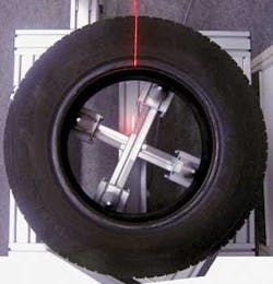
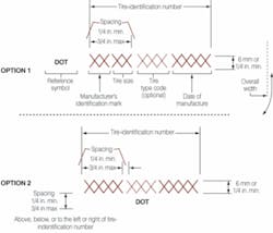
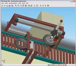
Recently, a German manufacturer of tire-mounting systems asked the Comovia Group, a 50-person project-management company that focuses on developing industrial-automation systems, to develop a system to automatically capture and analyze alphanumeric information, such as name of the manufacturer, type of tire, and US Department of Transportation (DOT) date codes, engraved on a tire by multiple mold inserts during manufacture (see photo). “In the manufacturing process,” says Tobias Berlin, managing director of Comovia, “molding systems create distinct markings on a designated position of the tire sidewall so that tire makers and their customers can trace the individual product years after the date of manufacture.” As well as providing information about the manufacturer, tire size, and type, the code also shows the date of manufacture (see Fig. 1).
“Because this information is so important,” says Berlin, “it is imperative that each mark can be clearly read during both automotive manufacturing and later in the after-sales market.” To do this, an imaging system must clearly illuminate the tire rim to increase the contrast between the raised or engraved serial numbers and the base of the tire. “Unfortunately,” says Berlin, “imaging these characters using standard light sources is very difficult, since the black characters on the tires’ black background absorb most of the light. If you then try to get a good contrast to read the characters, you are almost in hell!”

To overcome this problem, Comovia developed a prototype system that uses a laser-based illumination source, off-the-shelf CMOS camera, frame grabber, and PC-based software. Individual tires are mounted on a rotating platform above which is mounted a laser line generator and a CMOS camera.
Imaging marks
“To image the tire markings,” says Berlin, “the position of the tire must be properly calibrated with the image being acquired by the camera.” Using the output from the motor’s encoder, position information is input to the system’s C3-1280 CMOS imager from Automation Technology. “Because the system’s camera features an RS-422-based shaft encoder with tick counter and direction evaluation, no external hardware is required to determine the position of the tire as it rotates,” says Berlin.
A 50-mW Lasiris laser line generator from StockerYale illuminates the tire. “Because tires can vary in dimension,” says Berlin, “the system has to illuminate a laser line that can vary from 15 to 25 cm across the width of the tire. Because the light intensity of Gaussian-based lines is nonuniform, the calibration of CCDs can be difficult, requiring separate calibrations to be made for pixels in the bright central area and in the transition area. However, this can be overcome by using a non-Gaussian laser light such as StockerYale’s Lasiris, which produces more uniform illumination.
“As the tire rotates,” says Berlin, “the C3 sensor acquires height profiles and height images by means of a laser-triangulation technique.” In this technique, the laser line is projected on the image, and the resulting sensor image is evaluated by the C3’s on-board processor and output as raw 3-D data (see “What makes a smart camera smart,” above). By scanning the laser line over the object, a complete height image can be computed in the system’s PC.
Raw data
To compute these data, raw 3-D data are output from the camera over a Camera Link interface and captured using a PC-CamLink industrial PCI frame grabber from Dalsa Coreco. With support for clock rates up to 62.5 MHz, the PC-CamLink’s 16 Mbytes of on-board memory maintains the required data-transfer rates while minimizing CPU use and risk of data loss. Using this frame grabber, raw image data are bus-mastered directly to the host PC memory for further processing.
The raw image data consist of x, y, and z positional information and an 8-bit intensity level for each point on the scan. As data are acquired, the information is reformatted as a height profile for each line that has been scanned. “To generate an image from the data, a signal with as high a signal-to-noise ratio as possible is required,” says Berlin, “and a number of preprocessing steps are required.
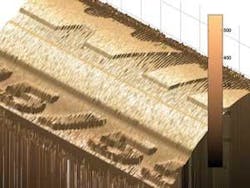
“To properly read the data marked on the tire,” continues Berlin, “a flat image is required in both width (x) and length (y).” However, because the tire is not an even surface, the light returning to the camera will not be evenly distributed. Thus, after the height profile is filtered to reduce the effects of random noise and specular reflection, the data must be normalized across the length and width (see Fig. 2). Because of the computational intensity of this process, this normalization is not accomplished on complete image data sets but rather in a piecemeal fashion using a moving window.
Adaptive thresholding
After filtering and normalization, data pertaining to the characters and numerals molded or etched into the tire must be extracted. “To do this,” says Berlin, “the PC software must selectively extract background data from the line profile.” To output a binary image representing the segmented characters on the tires, an adaptive thresholding method is used. This takes the image data as input and calculates a threshold for each pixel in the image. If the pixel value is below the threshold, it is set to a background value; otherwise it is assumed to be character or numeric data.
“Adaptive thresholding relies on the fact that smaller image regions are more likely to have approximately uniform illumination and are therefore more suitable for thresholding,” says Berlin. “By statistically analyzing the intensity values of the local neighborhood of each pixel, this threshold can be computed” (see Fig. 3). As can be seen, little noise remains on the flattened tire image. And, by using adaptive thresholding, the characters and marks engraved or molded into the tire can be clearly seen. “Once this grey-scale image data has been computed,” says Berlin, “the character data must be automatically read.”
Rather than develop its own optical character reader (OCR) software, Comovia implemented an OCR component from Cognex. “Because the Cognex Vision Library offers a number of tools including pattern-matching, 2-D symbol verification, and OCR as classes and functions implemented in C++,” says Berlin, “it was easy to implement the OCR function required, since many of the preprocessing functions such as adaptive thresholding had already been implemented in C++ by Comovia.”
To perform the OCR function, the operator trains the system to recognize known areas that contain alphanumerical data across multiple regions of interest within the area of the image. In this way, the system can perform multiple inspections on a single tire simultaneously. “To scan and compute the image data requires approximately 15 s on our prototype,” says Berlin, “about 10 s of which is required to scan the image and another 5 s to process the image data and perform the OCR. To reduce scanning time, in the future we want to use up to four cameras simultaneously and use PC hardware with more processing power to finally have all done in about 3 to 4 s. At the moment we are only doing this OCR stuff, but for the future we are thinking about doing surface or other quality checks inline in the production process of the tire. Because we have the whole tire in 3-D in the PC, we can perform many more tests and checking-it depends on what our customer needs”
False positives
“This process is time-consuming,” he says, “mainly because of the enormous amount of light required to illuminate the tire and the long exposure time required to capture the information.” Although the system can automate the process of OCR of tire data, a statistical analysis of the data obtained by inspecting multiple tires has yet to be performed. Although the customer may see the benefit of the system, we must also present them with a statistical analysis of false positives and false negatives.
“When developing these systems, there is a trade-off between false positives and false negatives (in which an actual match is not detected). Algorithms often can be made more sensitive, introducing more false positives, or more restrictive, rejecting true positives.” In the final analysis, it is the customer that must decide on the level of the system’s sensitivity.
To fully automate the prototype, the company is also developing a system that can be incorporated into a manufacturer’s production line (see Fig. 4). “In this way,” says Berlin, “tires can be automatically loaded by an operator or robot onto a conveyor where they will pass under the tire-inspection station.” By integrating the inspection station with such an automated conveyor system, automatic pass/fail mechanisms can reroute tires to different conveyor mechanisms depending on the pass/fail results.”
What makes a smart camera smart
One of the most important choices in developing a machine-vision system is specifying the correct type of camera to use. In the design of its laser-based inspection system, Comovia Group chose the C3-1280-CL CMOS camera from Automation Technology (Trittau, Germany; www.automationtechnology.de). Based on the PB13 1280 × 1024 × 10-bit CMOS imager from Micron Technology (Boise, ID, USA; www.micron.com), the C3 has been especially designed to target the 3-D structured light imaging market. With a Camera Link or USB interface and optocoupled trigger inputs, the camera’s on-board Spartan 3 processor from Xilinx (San Jose, CA, USA; www.xilinx.com) has been especially optimized to perform up to 28800 profiles/s with 36 million 3-D data points per second.
“What makes the camera unique are the parallel processors that have been incorporated to process image data at this extremely high data rate,” explains André Kasper, managing director of Automation Technology. In any laser-based imaging system, the height values of the object under inspection are determined by computing values determined by the focal length of the lens, the distance of the object from the camera, and the triangulation angle between the laser and camera.
When an image is scanned, the line profile is captured across the area array of the imager. Image data are then read from the imager ten columns at a time and read into ten corresponding pipelined processors embedded in the FPGA. “Each one of these processors is used to compute the position of the reflected light along these lines in a parallel fashion,” says Kasper. “Because the cross section of the reflected light is of Gaussian shape,” he says, “computing the actual position can be performed in several different ways.”
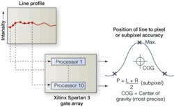
Perhaps the simplest of these methods is to detect the peak (highest intensity) pixel across the laser line, which results in a pixel-accurate value (see figure). Alternatively, a threshold value is determined and the threshold for the two points below which the Gaussian falls is computed. Averaging these two points provides an estimate of the center point of the Gaussian and results in subpixel-accurate measurement. Other methods can be used to provide greater accuracy. “By sampling multiple points along the laser line and determining the center of gravity of the Gaussian curve,” says Kasper, “the most highly accurate center point is determined.”
From the user’s perspective, all three methods of computing the position value can be obtained by configuring the camera using Automation Technology’s C3Lib API with source code. In the system developed by Comovia, these data points are output from the camera’s Camera Link interface and transferred to the host PC for processing. -AW
Company Info
Automation Technology
Trittau, Germany
www.automationtechnology.de
Cognex
Natick, MA, USA
www.cognex.com
Comovia Group
Karlsruhe, Germany
www.comovia.de
Dalsa Coreco
St.-Laurent, QC, Canada
www.imaging.com
StockerYale
Salem, NH, USA
www.stockeryale.com