Infrared system maps auto-parts stress
Camera, software, and lock-in module reveals potential flaws caused by mechanical stress.
By Pierre Bremond
Between the heat of the power train and the jolting of highway travel, automobile parts undergo significant stress. To validate automotive and component designs under these conditions, automobile manufacturers and suppliers use strain gauges or x-ray or ultrasonic imaging techniques to measure how stress and metal fatigue affect automobile parts.
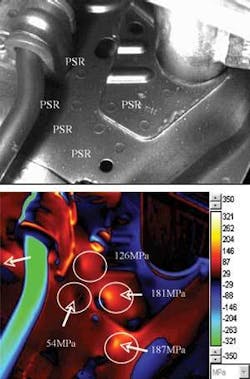
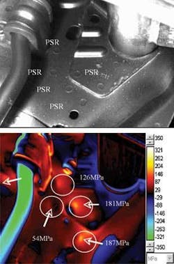
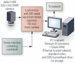
French automobile-manufacturer Renault wanted a cost-effective solution that could take finite-element-analysis (FEA) models from SDTools’ FEA add-on to The Mathwork MATLAB simulation software and compare these models against real-world measurements on tangible products during the automotive industry’s rapid-stress-validation process for new part qualification. Renault turned to Cedip Infrared Systems to construct a PC-host-based system that uses Fourier transforms (FTs) of passive IR images to measure small temperature fluctuations caused by mechanical stress applied to metal parts (see Fig. 1).
null
NEW NDT METHOD
To determine the amount of stress a metal part can take before reaching the fatigue limit, automobile manufacturers and suppliers have made physical impressions of parts before and after applying thousands of load cycles. Defects are located in the part’s impression before and after the testing, and changes in surface defects are used to measure the effect of the stress on the metal-an inexact science at best. Typically, measurements from several samples are combined in a Wohler curve, causing the total process to take several months.
Internal defects are more difficult to locate using standard stress-evaluation and imaging systems. Damage theory is based on assumed, discontinuous phenomena at microscopic levels. During cyclic fatigue tests, stresses at a macroscopic scale remain elastic; however, at the microscopic scale metals are neither isotopic nor homogeneous. They consist of random crystal organization, which induces local fluctuations in the microscopic stress field. As a result, local microscopic stresses can exceed the limit of local elasticity in certain, unfavorably oriented grains and induce local plasticity conditions, resulting in microcracks. Most microcracks stop propagating during the fatigue test, but some of them concentrate to form detectable cracks that rupture under additional stress.
Cedip’s Altair LI system uses thermoelastic theory, originally developed by Lord Kelvin in 1850 to make stress measurements and determine fatigue limits in materials based on the concept of dissipating energy cased by changing material densities (volume) under stress.
where Km is the thermoelastic coefficient of the material and
ρ = density (kg • m-3)
CP= specific heat (J • kg-1 • K-1)
Under adiabatic conditions, applying mechanical force to metal creates heat in the metal in real time that directly and linearly correlates to the amount of applied stress based on the material’s thermoelectric expansion coefficient. Stress concentration cannot be completely predicted using FEA, but by measuring the dissipation of heat energy over time and comparing that against FEA models, engineers can determine fatigue limits and stress responses of key mechanical parts.
Previous systems that measure the thermoelectric effect under dynamic loads used scanning optics with discreet detectors or thermocouples. Cedip designed the Altair LI system to measure thermoelastic properties in metal and other materials at each pixel across a camera’s full field of view by synchronizing nearly real-time temperature measurements with load cycles. The required thermal resolution to achieve a resolution of 1 MPa depends on the material properties through the thermoelectric constant coefficient (Km) for that material, but is typically equal to1 mK for steel and 2 mK for aluminum.
‘Locked’ Signals
The Altair LI system is built around Cedip’s Jade 550M 320 × 240-pixel or Silver 450M IR cameras. The mid-wavelength infrared camera uses an indium antimonide (InSb) detector to detect radiation between 3 and 5 µm and an electric Stirling cooler to reach a minimum thermal sensitivity of ~20 mK. InSb detectors are nearly as efficient at converting optical signals to electric signals as are the more expensive MCT (mercury cadmium telluride) detectors within this spectral band. Typically, forces upward of 100 MPa are applied to automotive products when testing the minimum stress measurement of the system, making the Altair LI system’s minimum 2 MPa force measurement sufficient for testing Renault’s crankshafts.
The Jade 550M works in passive mode without active IR illumination, collecting heat energy as it is generated by the metal surface under strain. The analog image data are fed via a 100-Kbit/s RS-422 cable to a lock-in thermography module located between the camera and PC host. The lock-in module converts the analog data to a 14-bit signal and then, using a field-programmable gate array (FPGA) operating at 20 MHz, applies a Fourier transform infrared (FTIR) to the amplitude data (see Fig. 2).
The FPGA decreases the amount of time needed to conduct the FTIR and improves stress measurements by allowing the measurement of changes in the heat distribution across the field of view. Cedip calls this methodology “D-mode” (dissipation mode testing). The technique can measure structures operating in real conditions instead of using the large number of test specimens required by conventional methods.
The lock-in module synchronizes the Fourier transform to the dynamic force applied to the part under test and filters out changes caused by movement of the part to create a 2-D stress map.
FTIR for fast testing
The Fourier transform converts the image data from temporal to frequency space. Where there is an internal defect, the variation of surface temperature is delayed over time. Because heat energy spreads in a sinusoidal wave, the delay is expressed in phase.
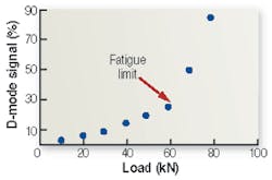
Cedip has created an algorithm that separates reversible phenomena, such as thermoelastic effects, from irreversible effects, such as intrinsic dissipated energy. There is a strong relationship between dissipated energy and plasticity, fatigue, and damage. Dissipated energy can be monitored to evaluate the limit of fatigue by analyzing the D-mode measurement versus level of stress applied to a single sample and to locate damage on real samples such as automotive components during fatigue tests (see Fig. 3).
To determine the operational range of the product under test in pounds per square inch (PSI), the Altair LI software includes the materials coefficient of thermoelasticity (Km) into its equation. The operator chooses the material type from a stored table, and the software includes the appropriate Km into its calculations. The entire process takes approximately 7 s from initiation to final result.
Renault uses the stress map to verify product designs, determine fatigue limits, and identify key stress or damage areas. This final measurement is critical because it allows production designers to build strain gauges into production lines at the most likely point on the part for stress damage.
Practical use of such a system in the automotive industry is limited by the large displacement of components under sine or road simulation load. Cedip is developing random motion compensation software that can compensate for all time-dependent load and displacement. After processing is complete, the result can be processed by Altair’s E-mode software to give the map of stress. In the case of sine load, a fatigue limit evaluation can be performed as described.
Pierre Bremond is sales manager industrial applications, Cedip Infrared Systems, Croissy Beauborg, France; www.cedip-infrared.com.
Company Info
Cedip Infrared Systems
Croissy Beaubourg, France
www.cedip-infrared.com
Renault
Guyancourt, France
www.renault.com
SDTools
Paris, France
www.sdtools.com
The MathWorks
Natick, MA, USA
www.mathworks.com