Shift/tilt lenses bring new perspectives
Shift/tilt lenses use an age-old principle to put products into focus.
By Andrew Wilson, Editor
Often in building machine-vision systems, designers are faced with problems that may at first seem insurmountable but can be overcome by the proper use of lighting and optics. While the correct choice of illumination will depend on the developer’s knowledge of lighting and lighting products, the proper option relies on understanding more about photography and the different types of available lenses, lens mounts, and image sensor formats.
Off-the-shelf C- or F-mount lenses that fit a number of CCD- and CMOS-based cameras can provide the correct depth of field, aperture, and focal length needed to image objects, often at high speed. Where perspective distortion needs to be eliminated for making precise measurements of mechanical and electrical components, for example, telecentric lenses can be used. In metrology applications, zoom lenses offer continuously variable focal lengths to change magnification while maintaining focus.
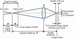
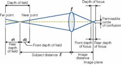
While these lenses provide benefits for specific machine-vision applications, most maintain their focus on objects that are perpendicular to the system’s optical axis. In these systems, the range to which an object can move along the optical axis and remain in focus is known as the depth of field and represents between the nearest and farthest objects that appear to be acceptable sharp focus. Among other factors, the depth of field depends on the focal length of the lens, its aperture, and the distance from lens to object (see Fig. 1).
Depth of field
To increase the depth of field of such objects, smaller lens apertures can be used. One of the drawbacks of increasing this depth of field, however, is that more light must be used, since the lens is stopped down. In Orson Welles’ motion picture Citizen Kane, cinematographer Gregg Toland overcame this problem using a fast film stock and large depth of field to render deep focus scenes of different planes within a shot simultaneously focused. Such depths of field can be automatically calculated using a number of online calculators, including Nicholas V. Sushkin’s Depth of Field Calculator (www.dof.pcraft.com/dof.cgi).
While the depth of field describes how well objects within the field of view will be in focus, depth of focus (or the depth of field at the sensor side of the lens) specifies the distance around the camera’s sensor in which the image will appear to be sharp. Depth of focus depends on both the size of the detector used and the focal length of the lens. Like depth of field, depth of focus can be increased by decreasing the aperture of the lens.
In image-processing systems, this is important, since the CCD or CMOS imager must maintain a level of flatness to capture images in proper focus from all regions of the image. In large-format lenses, where specialized mounts may be required to maintain a flat image plane, depth of focus may present a significant problem. On-line depth-of-focus calculators can also perform this calculation (see “Large-format-imager standard proposed,” Vision Systems Design, November 2005, p. 21).
Tilting lenses
Many machine-vision and image-processing applications use lenses that focus objects perpendicularly onto the object plane. To image objects that are not perpendicular to the optical axis, shift/tilt lenses can be used. “These lenses are used in machine-vision systems in which the object is viewed at an angle,” says Samuel Sadolet, director of product development at Edmund Optics.
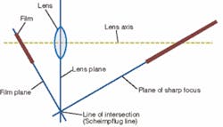
Based on optical principles patented in 1904 by Theodor Scheimpflug, an Austrian Army officer, the basic principle of shift/tilt lenses was described in a patent by Frenchman Jules Carpentier three years earlier. Scheimpflug’s British Patent (available at www.trenholm.org/hmmerk/TSBP.pdf) shows how, if a lens is tilted so that the plane of the lens intersects the film plane, the plane of focus must also pass though the same line of intersection (see Fig. 2).
In most machine-vision systems, cameras with lenses that are parallel to the sensor plane are most commonly used. To increase the depth of field of images captured with such lenses, the lens aperture can be increased until all the objects that need to be imaged are in sharp focus. However, there is only one true image plane that remains in sharp focus. While other areas within the image may be acceptably sharp, they deviate from the true plane of sharpness.
Because shift/tilt lenses use the Scheimpflug principle to allow the lens to be pointed at an angle to the plane of the sensor, they simply allow the plane of sharpness to be changed from being perpendicular to the camera’s imager to being at an angle to it. In his article Tilt lenses (www.photosafaris.com/Articles/TiltLenses.asp), John Shaw shows the photographic effects of using tilt lenses. The photograph was taken at f/8 with a Nikon 105-mm short mount tilting lens on a Nikon PB-4 bellows. With no tilt, the furthest film box is out of focus. When the lens is tilted, all the film boxes are in focus by altering the camera’s image plane. While this may appear at first to have increased the depth of field of the scene, in actuality, only the image plane has been changed.
For the designer of machine-vision systems, the tilt mechanism allows overall image sharpness to be controlled in a different way than conventional lenses. Used in conjunction with aperture, the tilt feature of these lenses allows objects or features within an image plane to be kept in focus. This is helpful when imaging objects at oblique angles. If absolute sharpness in the foreground and background is required, it is necessary to first focus on the closest foreground object and then tilt the lens until the background object is focus. After selecting the correct aperture, both objects will be sharp. Using such tilt mechanisms provides an additional means of controlling depth of field and allows greater freedom over the aperture and shutter speed combinations.
Shifting the plane
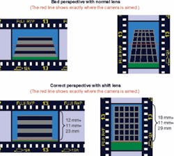
Current shift/tilt lenses also allow the lens to be shifted. Shifting of the optical axis from the center of the imaging plane allows perspective distortion to be enhanced or corrected. This is perhaps best highlighted in architectural photography, where lens shift can eliminate what may appear as a tilting of a building. This perspective distortion occurs because many such images are taken by elevating the camera from the horizontal image plane. By doing so, the captured image is not parallel to the object’s surface and not level with the center of the object, and any vertical lines will bend inward toward the top of the image (see Fig. 3). While the whole image may be captured, perspective distortion will occur.
To ensure that perspective distortion does not occur, a standard lens could be used. Because images must be captured parallel to the image plane, however, two possible solutions exist. Either the camera is moved back far enough to keep the whole scene in view while keeping the camera perpendicular to the object, or the camera is raised to a specific height to keep the whole image in the frame. With very large objects, however, this may be impossible, and using standard lenses may only image the bottom of such objects without incurring parallax distortion.
Shift lenses can be used to solve this problem. In standard 35-mm lenses, the 35-mm frame sits within a standard lens projection area. In a shift lens, the theoretical frame size and projection area are larger. This is one of the factors contributing to the greater expense of these lenses. However, incorporating such lenses into camera systems allows the user to move the lens off the axis of the lens mounting. This movement permits an area within the frame size of the shift lens to be placed over an area within the normal 35-mm frame.
Information about how much a lens can be shifted can be gained from the lens specification. For example, the ARAX 35-mm tilt/shift compact lens has a Canon-type tilt and shift mechanism that allows 11-mm lens shift and 8˚ tilt settings. Because 11 mm is the distance that the lens can move in the image plane, the resulting image moves exactly the same amount at the film plane, allowing objects to be imaged at closer distances to the object while maintaining camera-to-object perpendicularity and thus eliminating parallax effects.
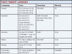
Of the available tilt/shift lenses, many are offered in wide-angle versions for architectural photography applications (see table). Others, however, may be suitable for machine-vision applications. “Canon’s lineup of three tilt/shift lenses also allows system integrators to obtain a wide depth of field, even at maximum aperture,” says Erik Widding, president of Birger Engineering. His company has developed an EF232 adapter that lets system integrators use and control Canon E-F-mount lenses without the use of a Canon EOS camera body (see Vision Systems Design, September 2005, p. 35). Shift and tilt adapters for a number of different camera mounts from companies such as Zörk Film & Phototechnic allow standard lenses to be adapted for this purpose. Although such lens systems are not inexpensive, they do provide another tool for systems developers to use when developing machine vision systems.
Company Info
Birger Engingeering
Boston, MA, USA
www.birger.com
Canon
Amstelveen, The Netherlands
www.canon-europe.com
Edmund Optics
Barrington, NJ, USA
www.edmundoptics.com
Hartblei
www.hartblei.com
Minolta
Ramsey, NJ, USA
konicaminolta.com
Nikon
Melville, NY, USA
nikonimaging.com
Pentax
Golden, CO, USA
www.pentaximaging.com
Schneider-Kreuznach
Bad Kreuznach , Germany
www.schneideroptics.com
Zörk Film & Phototechnic
Eugene, OR, USA
www.zoerk.com
