UV imaging opens new applications
Reflected-ultraviolet imaging is being enabled by advances in ultraviolet LEDs, laser sources, CCD cameras, and lenses.
By Austin Richards
Industrial machine vision has traditionally centered on visible-light imaging cameras and visible-light illumination. The simplest machine-vision applications are replacements for human workers, who see in the portion of the electromagnetic spectrum in wavelengths between 400 and 750 nm. A human-replacement machine-vision system might consist of a monochrome video camera combined with a software algorithm to detect the presence or absence of the cap on a tube of toothpaste and the degree to which it has been tightened. For a system like this, the lighting can be provided by simple tungsten lamps.
The machine-vision industry has done very well with this sort of application, using both color and monochrome video cameras that closely match the spectral response of the human eye. Yet there is a great deal of light in the electromagnetic spectrum that the human eye cannot see. This invisible light quite often carries significant amounts of interesting information.
Reflected-UV Imaging
Ultraviolet (UV) imaging has begun to emerge as an inspection modality for some industrial processes. Relative to x-ray or infrared machine vision, UV machine vision is still in its infancy, but the field is growing as commercial UV hardware drops in price and increases in diversity. New applications are emerging as more users integrate off-the-shelf UV cameras into production environments and experiment with them.
Ultraviolet light interacts with materials in a unique way, enabling features and characteristics to be observed that are difficult to detect by other methods. Ultraviolet light tends to be strongly absorbed by many materials, making it possible to visualize the surface topology of an object without the light penetrating into the interior. Because of its short wavelength, it tends also to be scattered by surface features that are not apparent at longer wavelengths. Thus, ever smaller features can be resolved or detected via UV light scattered off of them.
It is important to distinguish between reflected-UV imaging and UV-fluorescence imaging. They are different techniques with different characteristics, but because they both involve UV light, they are often confused with one another. Reflected-UV imaging starts with the illumination of a surface with ultraviolet light. The UV light is reflected or scattered and is then imaged by a camera that is sensitive in the UV band. The wavelength of the UV light is not shifted during the process.
UV-fluorescence imaging also starts with active illumination of a surface with UV light, but the detected signal is in the visible or infrared (IR) band. The fluorescent material absorbs the UV excitation, then reradiates at a longer wavelength. The emitted fluorescence is not reflected light-it tends to be a diffuse emission.
The UV band is rather broad, spanning the range of wavelengths between 10 nm (where the x-ray band starts) to the edge of human visual sensitivity at 400 nm. There are two main classes of industrial ultraviolet imaging applications, involving two different bands of the UV spectrum, and the cameras, optics, and illumination must be selected accordingly. The band of the spectrum between 300 and 400 nm is commonly known as the near-UV band. It is divided into the UV-A and UV-B sub-bands. Below 300 nm, standard optical glass becomes very absorbing. This region of the spectrum is known as the deep-UV (DUV) band, or alternatively, the UV-C band. Machine-vision systems in the DUV band generally operate around 250-280 nm.
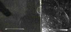
One of the most common applications for reflected-UV imaging is the detection of scratches in a surface. The shorter UV wavelengths tend to scatter more strongly off surface features compared to the visible or near-IR bands. So, for example, scratches not apparent in a visible image may be visible only to a person with excellent eyesight with great difficulty when visible light strikes at a very oblique angle. In contrast, in a UV image taken at 365 nm, the scratches can be seen quite easily (see Fig. 1).

As a result, UV imaging enables automated systems to detect scratches and digs on optical surfaces such as lenses or windows. In the semiconductor industry, photolithography requires inspection of photomasks with very fine lines and features to find defects that may be submicron in size. Confocal microscopes operating in the DUV band at 248 or 266 nm (laser wavelengths that can be generated by krypton fluoride and frequency-quadrupled Nd:YAG lasers, respectively) can be used to image these features with much greater clarity than in the visible band and can be used to find tiny defects in the silicon wafer starting material. Detection of these defects early in the production process can greatly improve yields and reduce waste.
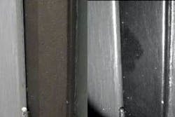
Other reflected-UV applications involve the detection of small amounts of surface contamination. Since UV light tends to be absorbed by organic materials, traces of oil or grease are sometimes detectable on many surfaces, particularly in the deep-UV band (see Fig. 2). It is also possible to distinguish new paint from old in some situations, even when the two types of painted surfaces look identical in the visible band (see Fig. 3).

null
Sensors and Lenses
Most CCD and CMOS imaging cameras do not image well in the UV band, by design. Ultraviolet light is considered undesirable in monochrome or color video cameras, because standard optics do not simultaneously focus both the visible light and the UV light in a scene. Any UV sensitivity in a CCD camera may result in purple halos around point sources and an overall softening of the image. To eliminate this effect, sensor packages in many CCD and CMOS cameras have built-in UV-absorbing features in them to prevent UV from being detected.
To image in the UV band, one needs to use CCD and CMOS imagers that do not have these blocking features in the optical path. Therefore the machine-vision system integrator should select cameras that are specifically designed for ultraviolet sensitivity in the band of interest, rather than trying to use a visible-light camera. It is sometimes difficult to get definitive information from UV camera manufacturers on sensitivity and complete spectral response, and some trial and error may be required.
The two bands of interest in machine vision are the near-UV and the deep-UV bands. The near-UV band is fairly well transmitted through glass lenses and can be detected reasonably well by standard CCD cameras (provided they do not have UV-blocking features) without special thinning or wave-shifting coatings, though the response rapidly rolls off at the short-wavelength end of the band. If glass lenses are used, they should actually be cheaper lenses without high-quality antireflection coatings. High-quality coatings are designed to reflect UV light away from the sensor and have less UV transmission. Inevitably, using standard color video lenses in the UV band involves trade-offs between performance and cost. One may notice slight ghost images formed by reflections from uncoated lenses, and overall transmission will not be as good as specially designed UV optics. But the cost is significantly less.
In contrast, the deep-UV band absolutely requires special sensors to detect UV light with wavelengths below 320 nm. Below that, standard silicon CCDs are quite insensitive. To increase their responsivity, they must be processed differently. One method is to thin the silicon substrate substantially. This allows UV light to penetrate the substrate and get in close to the active layer of a photodiode device. Carriers generated by the photons can then be swept into the junction, resulting in photocurrent.
Another method involves coating the substrate with a wave-shifting coating such as Metachrome II or various phosphors. These coatings fluoresce in the visible portion of the spectrum. The fluorescence signal can traverse the substrate more easily than short-wavelength UV and, therefore, is detected. The disadvantage is that half the light generated by the fluorescence process radiates away from the sensor and is never detected. The coatings also degrade the MTF of the camera system and can introduce image-retention issues if the camera is running at a high frame rate.
UV cameras are back-illuminated. Commercial back-illuminated UV cameras can have quantum efficiencies (QEs) of 60% or better down to less than 200 nm. High QE is important for deep-UV work, in particular, since few photons are reflected off surfaces, and deep-UV light sources have a high cost per watt of illumination. Commercial back-illuminated cameras are available with 60-Hz frame rates for high-speed inspection systems.
Standard glass lenses will not work well in the deep-UV band, since the typical lens glass absorbs strongly below 300 nm. Special lenses made with quartz (fused silica) or calcium fluorite are required. There are few off-the-shelf sources for these lenses, and the cost is quite high compared to visible-light optics. Microscope objectives are available for confocal microscopes operating in the DUV band.
Light Sources
Traditional light sources for UV work are all based on gas-discharge tubes. These tubes sometimes look like purple or pale-blue fluorescent light tubes. Tubes with mercury vapor generate UV light in the 365-nm band, and different gas pressures in the tubes can change the wavelength of UV light emission.
Gas-discharge tubes suffer from several disadvantages. The output is relatively weak compared to solid-state sources, and the illumination angle is quite wide, making it difficult to achieve high-intensity illumination. The output spectrum is quite wide, since there are many emission lines in a gas discharge. If monochromatic UV is required, then the output of the tube must be filtered. They are also fragile, require hazardous drive voltages, and have limited lifetimes, particularly in the case of xenon short-arc lamps.
In recent years, high-brightness UV LEDs have become commercially available and are starting to displace gas-discharge tubes in a variety of applications. These devices are based on gallium nitride semiconductors and can be found in wavelengths down to 365 nm, although today the most common UV LED wavelengths are 370 and 395 nm. The light from these sources is highly monochromatic due to the nature of semiconductor light sources that have an energy bandgap.
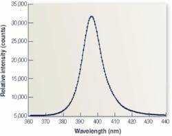
Recent measurements on a 395-nm LED show a full-width at half maximum result of 14 nm (see Fig. 4). Solid-state UV lasers have even narrower spectra and higher beam intensities, making them attractive for illumination in reflected-UV microscopy. Excimer lasers operating at 266 nm are used in conjunction with confocal microscopes with special UV optics to inspect photolithography masks for defects and to detect surface defects in semiconductor starting material.
Monochromatic UV sources such as lasers and LEDs are desirable in machine-vision applications, because the optics used on the camera do not have to be achromatic, which lowers their cost significantly. The images formed with monochromatic illumination are sharper than images made with broader UV sources. Narrowband filters can be used on the camera optics, but narrowband UV filter systems generally require auxiliary filters in the stack to block out-of-band light, reducing transmission at the center wavelength.
Several manufacturers of machine-vision lighting are packaging UV LEDs in lamp assemblies that are driven by current sources running on 24 Vdc. These light sources make it possible to direct intense, narrowband UV light onto objects under inspection, which can be moving along a conveyor belt. The lamps can be strobed to increase the peak brightness while an image is taken.
Generally speaking, as wavelengths get shorter, material absorption increases. This helps image the surface topology of materials such as BK-7 glass and makes it easier to see smaller surface features. The cost of imaging in the deep-UV is higher than near-UV imaging, because the components used in a deep-UV imaging system are more expensive and exotic. Finally, long-term exposure to deep-UV tends to degrade sensor performance over time, requiring camera replacement.
Reflected-UV imaging is a relatively new area of machine-vision technology. Advances in light-source technology are driving down costs of systems, and commercial hardware is becoming more available. There are still many undiscovered applications for reflected-UV imaging, and it will be interesting to see these applications move from an R&D environment into process inspection.
Austin Richards is chief technology officer at Oculus Photonics, Goleta, CA, USA; www.ultravioletcameras.com.