Machine vision speeds PCB solder-joint inspection

FireWire camera, telecentric lens, custom lighting arrangement, and servo system checks automotive-connector integrity.
By Andrew Wilson, Editor
Printed-circuit boards (PCBs) destined for deployment in automotive applications must be manufactured to rigorous and exacting standards and meet the harsh environments that include vibration and temperature challenges. To ensure that any vibration does not cause structural defects to emerge after installation, PCBs use rugged high-density connectors that are mounted with plated-through-hole techniques. Before each PCB is finally assembled, each board must be tested to ensure correct operation and that each surface-mount solder joint is properly formed, guaranteeing a proper interface to the outside connector.
“In the past,” says Andrew Waller, a director of Industrial Vision Systems (IVS), “a simple continuity check was used to test the functionality of each board.” To do this, the board was mounted in a nest and a mating connector attached to the board. Because multiple point-to-point connections are made, the electrical path between multiple points could be made rapidly. “However,” says Waller, “if dry solder joints exist that form the contact between the electrical components and the connector on the PCB, any large temperature changes may cause intermittent failures.”
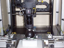
To overcome these challenges, IVS has developed a system that combines continuity testing and solder-joint inspection in one unit (see Fig. 1). Dubbed AutoVision, the system is currently being used to automatically check 150 pin automotive PCBs at the rate of approximately three per minute. “However,” says Waller, “because the system has been built in a modular fashion, it can be easily adapted for many different types of PCBs and connectors.”
Continuity check
“To speed the throughput of PCBs,” says Waller, “it is important that the continuity check is performed simultaneously with solder-joint inspection.” To do this, a PCB is first loaded into a nest in the AutoVision system. After each part is loaded, the part must be inspected to ensure that the correct one has been placed in the nest. “Because each part is barcoded and the position of each barcode is known, it is possible to verify whether the correct part is in place before any continuity check or solder-joint inspection is made.
A MS3 barcode reader from Microscan Systems is mounted on the x-y-z stage of the machine-vision system. Interfaced to an industrial PC over an RS-232 serial interface, the barcode reader is positioned over the barcode, and the part number and type are read. This information is then used to inform the operator whether the correct part is in place. After each part is verified, it is then automatically clamped into place using a mating connector mounted on one side of two linear stages. Once mounted, a third-party continuity tester running on a separate PC performs the continuity test of the PCB. Results of this test are transferred to the industrial PC over an RS-232 interface.
“While the continuity tester performs an electrical test on the part, an integrated machine-vision system inspects the solder joints on the PCB. “Solder inspection is one of the most complicated machine-vision tasks,” says Waller, “primarily due to reflections from metal, the nature of the solder flow, and possible solder flux that may be present on the part.”
Solder inspection also requires high magnification of the solder joint to accurately confirm whether a joint is good or bad. To do this, light must be concentrated around the joint with a combination of darkfield, on-axis, and direct LED lighting. Individual images captured using a variety of these techniques can then be processed using different software routines.
To properly image the solder joints, IVS mounted a 752 × 582 × 8-bit FWX06c color FireWire camera from NeuroCheck with a 0.5-1 × 50-mm TC5028 f/2.8 telecentric lens from Navitar on an x-y-z servo system. A custom lighting arrangement consisting of a DL201 white dome light from Metaphase Technologies, a shower light, and a red ringlight from CCS America was used to properly illuminate the part (see Fig. 2).
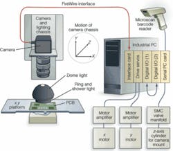
Says Waller, “The ring and dome light are run independently so that while the dome light can generate a darkfield image of the solder joints, the ringlight provides direct on-axis illumination. This combination allows subsequent image-processing functions to determine whether solder or solder pins are missing or whether too much solder has been applied to the PCB.”
To transfer images from the FireWire camera to the industrial PC, IVS used an EX-6500E three port FireWire interface board from Exsys housed in a single slot of the system’s six-slot PCI industrial motherboard. “Because industrial PCs generally do not feature FireWire interfaces as standard,” says Waller, “a separate board was used to interface the camera to the host CPU.” This same CPU was used to control the motion of the x-y-z stage housing the lighting and camera system.
Motion control
Perhaps one of the most interesting design engineering aspects of the system was how IVS combined the motion control required with the machine-vision system. To control the motion of the x and y stage, the host CPU uses an ME-8100 optoisolated digital I/O board from Meilhaus Electronic. This, in turn, drives a U500Plus PCI servomotor controller card from Aerotech that is also housed in the industrial motherboard.
By interfacing this board to two Omron 400-W stepper motors through a drive amplifier, also from Omron, the position of the x and y stage can be controlled using host-based software. Similarly, the ME-8100 board also controls an SMC air manifold on the z-axis. “Because the camera is only required to move between two positions in the z direction,” says Waller, “a simple air-manifold can be used.”
To control the operation of the x, y, and z stages, IVS developed custom software with Microsoft Visual Basic. “Using this solder vision tester software running on the host PC,” says Waller, “individual positions in the x, y, and z axes can be controlled on an individual basis. These commands are then interpreted by the Aerotech servo controller to drive the x-y stage to preset positions as required.”
One of the challenges faced in developing the system was integrating the motion control and vision system. “Rather than develop a single program that integrated motion control and vision,” says Waller, “two separate programs were designed.” These were the motion-control software written in Visual Basic and custom image-processing routines developed using the NeuroCheck machine-vision software.” To communicate instructions between these two programs, IVS opted to install a second ME-8100 optoisolated digital I/O board in the host computer.
“Rather than develop software to pass instructions between the motion control and image-processing software, the individual software elements communicate using the I/O ports of the digital I/O boards. “Although perhaps not quite as elegant as a software-only approach,” says Waller, “it was far simpler to develop the system by passing individual commands over I/O interfaces.”
Seeing solder
After the barcode reader has verified the presence of a correctly clamped part, the x-y-z gantry housing the machine vision camera and lighting is moved into position. “Because the dimensions of the part are known,” says Waller, “the camera system is first directed to a known (x, y) datum point in which the first four sets of pins are to be imaged.” However, because of any possible error that may exist in the motion-control system, a feedback loop must be used to properly check this location. By imaging fiducials on the PCB, this offset is computed and adjusts the motion-control system to compensate for any future errors.
After any error is compensated, an image is taken of the first four pins on the PCB within a field of view of 9 × 10 mm. “Each check within the global check routine of NeuroCheck offers a set of image-processing functions to allow faults to be measured. This is first done by defining known regions of interest (ROIs) around each of the pins. Any background effects are then eliminated within each of the ROIs by applying a smoothing function. Each region is thresholded to create a binary image of the solder joint.
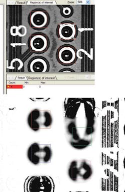
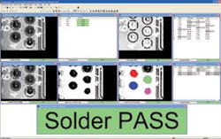
“Based on the binary image and the original ROIs, NeuroCheck software searches for dark objects within each ROI. “Because each of these dark objects has known perimeter and area values,” says Waller, “the data extracted can be compared with information from a known good part.” These screening levels for failure can be set by the user to allow flexible quality control. This process is repeated for a number of different lighting conditions (see Fig. 3). After four sets of pins are examined, the data are recorded and the camera moved in a serpentine fashion to examine the next set of four contacts on the board. During this time, a human-machine interface (also written in Visual Basic) is updated and the results of the testing process and the continuity check displayed in real-time (see Fig. 4). Finally, all the images and data are automatically saved to provide historic process control data for the company’s quality control department.
null

null