System discriminates hard-to-separate colors

One of the main problems for color machine-vision systems is distinguishing objects with similar colors. “This problem occurs,” says Andy Long, senior director of Cyth Systems (San Diego, CA, USA; cythsystems.com), “because of the way in which the human eye interprets color.” The eye contains three color receptors, so the brain interprets color in terms of these tristimulus values. But, because each cone responds to a number of wavelengths, different combinations of wavelengths of light produce similar tristimulus values and are thus interpreted by the brain as being the same color. When two colors with different spectral power distributions appear to be the same color, they are said to be metamers.
“To distinguish between colors that appear similar,” says Long, “developers of color machine-vision systems must be careful to choose the correct type of lighting.” In many systems, using an opposite light spectrum will make a feature appear darker, while using the same spectrum will make it appear brighter. Unfortunately, this only forms a rough basis on which light sources will best match any given application. To discriminate between colors that are closely matched, a number of different light sources can be used, including quartz-halogen and LEDs.
“As a standard for comparing different light sources,” says Long, “color is determined using a blackbody radiator, where the temperature of the radiator emits a specific frequency. However, although incandescent lights closely follow this model, fluorescent lamps do not emit radiation in the form of a blackbody curve.” To categorize them, they are assigned a correlated color temperature (CCT)-a color temperature of a blackbody that closely matches the lamp’s perceived color. “However, simply specifying the CCT does not reveal the type of illumination used,” says Long. “In fact, a variety of lamps could all be specified with the same CCT but exhibit radically different color spectrums.”
To show the effects of metamerism using two different light sources, Cyth Systems demonstrated two types of illumination systems at NIWeek (Austin, TX, USA; Aug. 5-7, 2007). The uncommercialized prototype used NI’s Vision Builder for Automated Inspection and the Cyth Vision Builder 4 Automated Inspection ExpressPlus Step software to display a single metameric image.
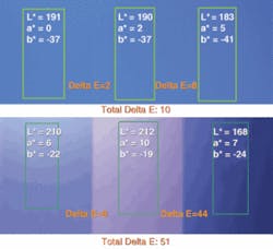
Rather than use the CIE x-y-z color space, the company transformed the coordinates into the more commonly used Lab coordinate space to display the results of the inspection. When viewed under an LED light source it can be seen that the total ΔE value describing the color difference between the left and right side of the image was just 10. When viewed under a quartz-halogen source, however, this ΔE increased to 51, making the color differences more easily detectable (see figure).
At present, to properly illuminate such color requires the developer to experiment with a number of lights that may have different CCTs and color spectrums. But at NIWeek, Cyth Systems described an automated system based around the Chameleos LED illuminator from Edmund Optics (Barrington, NJ, USA; www.edmundoptics.com). “By combining the light from red, green, and blue (RGB) LED sources that are all individually controllable,” says Long, “it is possible to automatically control the color spectrum using the digital interface of the Chameleos.” In this way, the developer can generate a color spectrum to more accurately discern colors that are closely matched.
Cyth Systems wrote a demonstration program in NI’s TestStand software that automatically cycles through each RGB color in turn. Reflected color information about the part under test can then be captured using a solid-state camera. By computing the color histogram of each color component at every part of the test process, the largest ΔE value for a given RGB combination can be determined. The integrator is then free to match the color components to more easily detect any color differences among parts.