High-speed imaging helps check fly flight
Andrew Wilson, Editor, [email protected]
Researchers at the Institute of Robotics and Intelligent Systems (www.iris.ethz.ch) and the Institute of Neuroinformatics (www.ini.unizh.ch; fly.ini.unizh.ch) at the Swiss Federal Institute of Technology (ETH; Zurich, Switzerland) recently deployed a high-speed vision system for real-time analysis of the wing kinematics of tethered flying fruit flies. In combination with synchronous lift measurements using microelectromechanical-system force sensors and real-time sensory stimulation in a flight ‘simulator,’ these measurements provide a better understanding of the neural processes underlying the maneuverability of fruit flies. “Such an understanding has potential applications in the development of autonomous microrobots,” says Chauncey Graetzel of ETH, “where modern control strategies are typically less efficient and more computationally expensive than in fruit flies.”
Fruit flies offer a particularly interesting model for exploring biomimetic design principles in microrobots due to their precise wing movements and specialized neuromotor control system. To study their flight biomechanics, Graetzel and his colleagues have developed a high-speed computer vision system that uses a camera with dynamic regions of interest (ROIs). Using an extended Kalman filter to fit previously known wing-position measurements, the position of the next ROI can be predicted. “This allows sampling of the wing position at 6250 frames/s using a ROI of approximately 3600 pixels, more than four times faster than other current high-speed vision tracking systems,” says Graetzel.
Graezel and his colleagues chose a Trackcam camera from Photonfocus (Lachen, Switzerland; www.photonfocus.com) fitted with a VZM 300i zoom lens from Edmund Optics (Barrington, NJ, USA; www.edmundoptics.com). Digitized images were captured to an Intel Pentium IV 2.8-GHz PC with 512 Mbytes of RAM via a Camera Link interface connected to a Micro Enable III frame grabber from Silicon Software (Mannheim, Germany; www.silicon-software.com).
To image the beating wings, a fly was immobilized on a cooling stage and glued to a tungsten wire using a MP285 micromanipulator from Sutter Instrument (Novato, CA, USA; www.sutter.com) to position the fly along its six degrees of freedom. It was positioned so that the wing stroke plane coincided with the camera plane. To provide rear illumination, an ACE 150-W halogen light source from Schott North America (Auburn, NY, USA; www.us.schott.com) was used with a fiber bundle to guide the light under the tethered fly. Diffusive tracing paper was placed 15 mm in front of the light source to provide intense and homogenous backlighting. An additional 650-nm high-bandpass filter was used to eliminate the wavelengths perceived by the fruit fly’s visual system.
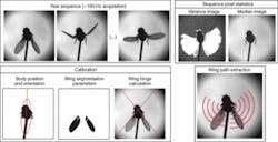
To extract the position and orientation of the fly’s body, the path of each wing and the visual properties of the wings and background must be determined. To do this, a calibration procedure generates a sequence of pixel locations describing the typical path of each wing. This is used during tracking to target the relevant pixels for image processing. Fifty 1024 × 1024-pixel images are acquired at random and a statistical analysis of the values of each individual pixel location is made throughout the sequence.
While the median value of each pixel builds the background image, the standard-deviation image is binarized and used as a mask to isolate the wings from the rest of the image. To segment the body of the fly, the median image is thresholded and morphological operators applied to eliminate small blobs. Then, size and position criteria are applied to the remaining blobs. Once the blob containing the body is identified, it is used as an additional mask to isolate the wings.
To segment the wings and calculate the wing path, the background image is subtracted, and a quantization algorithm is applied to calculate an optimal binary threshold value to generate binary images representing the isolated wings. To eliminate possible holes within the wing blobs caused by their semitransparent nature, a morphological opening is applied, followed by a Canny edge detector to isolate the wing edges. A Hough transform extracts the strongest line on each side of the fly’s body. This line, in 80% of the cases, corresponds to the leading edge of the wing. The intersection between each strongest line of the sequence is calculated and the median intersection is taken as an estimate of the wing hinge position (see figure). This information is used to predict the future position of ROIs.
To program the PC, Graetzel and his colleagues used Microsoft’s Visual C++ development environment and the Open Source Computer Vision Library from Intel (Santa Clara, CA, USA; www.intel.com/technology/computing/opencv). Tracking typically lasted 30 s, during which the images were transferred to the frame grabber’s buffer and processed. To avoid timing problems, the frames were acquired continuously. In practice, no frames were dropped.

