Lens considerations change for large-format cameras
While advances in sensor technology have opened new applications for machine vision, the ability of a lens to interface with these sensors has lagged behind.
By Jeremy Govier
In the past, most machine-vision sensors were typically smaller than a 12-mm image circle, with line sensors less than 2000 pixels and area sensors with 4 Mpixels or fewer. Recently both line and area sensors have rapidly increased in size from 20 up to 90 mm, while pixel count has increased up to 12,000 pixels for linescan cameras and up to 16 Mpixels for area-array cameras.
While this advance in sensor technology has opened up many new applications for machine vision and scientific imaging, the ability of a lens to interface with these sensors has lagged behind. One of the hurdles in developing lens options to meet the expanding range of sensor options has been the difficulty of designing new lenses. For example, keeping lens resolution down to the size of the new pixels and greater than very large image sizes is especially demanding on the optical designs.
In addition, many of the particularly difficult-to-control lens errors are dependent on the image size, and controlling these requires more lens surface, more expensive assembly processes, and, in some cases, more difficult-to-manufacture elements such as aspheres. With these limitations in mind, it is important to understand the key parameters for lenses, including size, resolution, field coverage, f#, and evenness of illumination and how they affect the application.
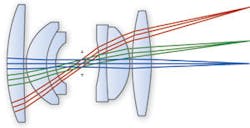
The important size considerations include the working distance, total track, and diameter of the lens and mount. The working distance is the distance between the lens and the object (see Fig. 1). This may need to be large for some applications to ensure there is enough room for illumination, handling tools and the unit under inspection. Total track is the total distance between the object and sensor and may need to be minimized because of size constraints in the machine or environment the lens will be used in. The diameter of the lens and mount is often important to allow multiple cameras to be placed close enough together for a continuous image.
Resolution is a lens’s ability to transfer image detail. The resolution of the lens is the size of the smallest image feature that needs to be seen or accuracy of a measurement. This can be defined as the object resolution, which is the feature size on the object, or the image resolution, which is the pixel size of the camera. The magnification of the lens is used to relate these two numbers. Pixel sizes for most large-format lenses are on the order of 5 to 7 µm.
The field coverage is the area over which the lens can maintain the resolution. In general, it is easier to maintain a higher resolution near the center of a field, while the performance will fall off further from the image center. For large sensors, this is more acute as it is difficult to maintain a high resolution all the way to the edge of the field. However, this is important for machine-vision applications, because the whole sensor is typically used for gauging and other applications. Therefore, using a lens not designed for a large sensor will result in resolution falling off significantly at the edges, reducing the accuracy of the imaging results.
Light-collection ability of a lens is described as f#. The smaller the number the more light is collected. The f# of lenses is related as an inverse square of the amount of light they collect. For example, an ƒ/8 lens is 2x the f# of an ƒ/4 lens, but it collects one-fourth the light. The f# of a lens is important in a machine-vision system because it controls how quickly parts can pass by the camera, decreasing the exposure time on the camera and allowing faster inspection times.
Evenness of illumination is much like the field coverage in that it defines how the light collection varies over the field of view. There are two main factors that can limit the light collection further from the center of the image. Vignetting can be intentionally designed into the lens to improve image quality by blocking rays that would degrade the image quality, but it can also unintentionally be introduced into the system by the use of mounting adapters and by using a lens outside its design specification.
The other factor is a physical phenomenon caused by the angle the light strikes the sensor, which is often referred to as “cosine to the fourth falloff.” This is defined as the relative intensity of the same amount of light that strikes perpendicular to the sensor to the amount of light that strikes at an anglex equal to cosine4(x). For example, a lens where the light at the edge of the field has an angle of 30º is 56% as intense as light at the center of the field where it strikes perpendicular to the sensor (see Fig. 2). So a lens that is not designed to control the ray angles will start off with a significant drop in light collection over the field even before any vignetting (see “The lens-shading challenge,” p. 28).
Lens availability
Lenses available for solving machine-vision applications are typically designed for either machine vision or photography. The advantage of a lens specifically designed for machine vision is that it is optimized to get the best performance in most industrial applications, while the disadvantage is that it is designed almost exclusively for C-mount cameras, limiting the options available for large sensors.
Photographic lenses are generally more available for larger sensors, particularly up to 35-mm images/43-mm image circles, but they lack image quality over the entire sensors, since the human eye will concentrate on the center of the image. Photographic lenses also tend to vignette significantly; the eye may ignore this, but a thresholding algorithm in a machine-vision application will give erroneous results. In addition, most photographic lenses are designed for low-magnification images from a long distance, thereby making it difficult to maintain resolution when used close to the object in a higher-magnification application.
Because of these limited options for large-format sensors, a compromise of the important parameters needs to be made. If the resolution and light collection over the entire image are important, the size of the system may need to be increased. Also, to get good resolution over the entire field, the f# may need to be increased because resolution tends to suffer at low f#. The important thing in integrating a machine-vision system is to prioritize these requirements to find the best solution.
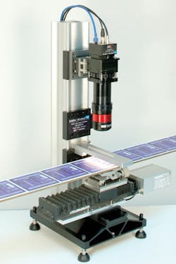
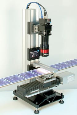
When designing a custom lens for a specific application, we often are given strict requirements on size, resolution over the entire field, and evenness of the illumination (see photo on p. 27). Usually the mounting requirements of the lens and the defects or feature size measurements are rigidly defined.
With these parameters in mind, we must determine how low an f# we can obtain. The minimum amount of light that can be collected over any point in the field will determine the speed of the system because providing an ƒ/2 lens at the center of the field that only receives one-quarter of the light at the edge of the field may not be better than a ƒ/4 lens that has very even illumination.
Lens mounting
The mounting of a lens to a camera has become one of the major challenges in selecting a lens for a large-format camera. There are dozens of mounting options for the various large-format cameras, ranging from old SLR photographic lens standards such as the Nikon F-mount to nonstandard bolt patterns and thread options. All have different flange distances that put the lens in the correct position away from the sensor.
The flange distance can be extremely important. If the camera requires a very long flange distance, there may not be enough room to adapt the lens to the camera mount. Some cameras have identical threads for their mounts but different flange distances so the lens may not be in the correct location and could give the wrong magnification or focus.
In addition, sometimes the size of the mount of the adapters needed to attach the lens to the camera mount will block some of the light that would normally form the image. This vignetting effect can cause dark edges on the image.
Since there is no definitive standard for the mounts, there are options users have for finding the mount that matches their camera and the lens they want to use. Many camera makers have adapted the F-mount because there are many F-mount lenses available that were designed for the photographic market.
This also poses a challenge for the lens manufacturers, because there are so many choices as to what mount they should design their lenses for. With many cameras using F-mounts, it is desirable to design a lens for the popular mount, but the long flange distance leads to larger lenses, often a compromise in design, and may limit the size of a sensor the lens can cover.
These design constraints have led lens manufacturers to produce lenses with the minimal mount and customers to fit their own barrels between the camera and lens. Another option is making very complicated and extra large mounts that can be adapted to many different cameras. Both camera and lens manufacturers desire standardization to the mounting, but there still is no popular standard.
JEREMY GOVIER is director of design services at Edmund Optics, Barrington, NJ, USA; www.edmundoptics.com.
The lens-shading challenge
“When selecting suitable lenses for cameras with large-format image sensors, such as the Kodak KAI-11000, machine-vision and image-processing designers must consider any effects that may occur due to lens shading,” says Gerhard Holst, head of research at PCO Imaging. “This effect describes the result of various physical phenomena such as lens vignetting and variations of the quantum efficiency of the sensor due to on-chip micro-lenses. Such shading results in light falloff toward the edges of a digitized image.”
One source of shading is introduced by the camera lens. This lens vignetting describes how outer portions of the image ray bundle are internally blocked by the inner aperture of the lens. The inner aperture blocks the outer rays, and, as a result, more light rays from the center of the image reach the image sensor. When the adjustable aperture (f-stop) is closed down, the ray bundle becomes more restricted towards the center resulting in minimal or reduced vignetting. A second source of shading is the angle of view of the lens. The smaller this angle, the more parallel light rays reaching the sensor will be. Thus, the longer the focal length, the less vignetting occurs.
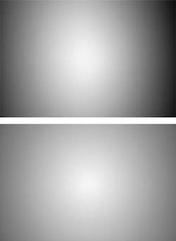
Using a camera with a KAI-1100 image sensor and both a 50- and 200-mm ƒ/1.4 lens highlights these phenomena and shows the vignetting of a 72% intensity drop for the 50-mm lens and a 45% intensity drop for the 200-mm lens (see figure). Thus, the longer the focal length, the less the shading. If the aperture is closed to ƒ/8 in both cases, the shading is decreased to 70% for the 50-mm lens and 15% for the 200-mm lens.
Using a Nikon 50-mm lens, the intensity falloff is always worse than the published datasheet values, and using a Zeiss 200-mm lens, the results are very similar. Also, when using a 50-mm lens, the horizontal profiles and vertical profiles are very different, while for 200-mm they are clearly matched. This can be explained by the influence of microlenses contained on the image sensors. These lenses focus incoming light onto the light-sensitive part of the pixel, resulting in a quantum efficiency increase of the sensor.
With microlenses, the peak efficiency of the Kodak KAI-2001, for example, is about 58%, while without microlenses it is 10%. This is due to the small fill factor of the pixel. Additionally, because the microlenses are single lenses, they do not properly focus light rays that impinge under larger angles resulting in a dependence of the quantum efficiency to the angle of incident light.
This dependence is caused by the geometrical distribution of the light-sensitive area in a pixel and the imaging characteristics of the microlenses. If the angular incidence of the incoming light rays fits the imaging characteristic of the microlens, the light rays are properly focused. If the angle of incidence becomes larger, the light rays are imaged outside the sensitive area and strike the nonsensitive part of the pixel resulting in reduced quantum efficiency. Similarly, the difference between the horizontal and vertical quantum efficiency results from the geometric layout of the image pixel.
The use of lenses with a long focal length at a small aperture minimizes the shading problem dramatically. However, for practical applications, the use of telephoto lenses is not possible, and ƒ/8 aperture stops may not be practical for all machine-vision and image processing applications. Because of this, a number of companies, including Ingenieurbüro Eckerl have developed low-shading lenses for 1-in. image sensors. Lenses for image sensors beyond 1-in. are currently in development.-A.W.
