X-ray system measures surface density
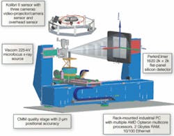
To achieve high resolution, an x-ray CT system is combined with a virtual CT system and Kolibri optical CMM system.
By Kai-Udo Modrich
Computed-tomography (CT) systems can nondestructively image hidden features by reconstructing a three-dimensional (3-D) model out of two-dimensional (2-D) x-ray images, but CT systems suffer from poor dimensional accuracy. X-ray sources for CT systems emit broadband radiation rather than monochromatic radiation, resulting in different attenuation of x-ray photons with varying energies. This “beam hardening” effect occurs because of the additional attenuation exhibited by low-energy x-rays and is one of the main causes of errors in a final 3-D reconstruction.
Another important variable is the threshold value that marks the boundary between the product and the surrounding air. Typically, the density threshold value that marks an object’s surface location is set locally by an operator based on a review of the reconstructed but unrefined 3-D reconstructed scan. Operators often change the value for different parts of the scan to make the CT reconstruction more subjectively accurate; however, operator-set values can yield unrepeatable results that are determined by instrument and technician. On the other hand, the threshold can be set to a global value for the entire product surface, but both approaches reduce dimensional accuracy of the CT scan by introducing artifacts or computer-generated error into the 3-D measurement.
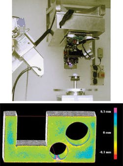
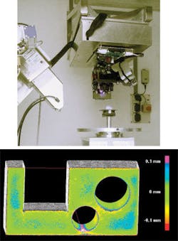
Work at the Fraunhofer Institutes has proven the effectiveness of combining CT and Kolibri-type coordinate-measurement-machine (CMM) systems to automatically correct for beam hardening, while objectively determining surface threshold densities, resulting in CT scans with dimensional accuracy down to 10 μm. The system was recently tested by measuring large (L = 800 mm) aluminum test objects, proving that two metrology sensors, when properly registered, are better than one.
Three-dimensional reconstructions are created by taking multiple 2-D images of the same object from different angles and then using Beer’s Law to reconstruct the full 3-D volume from the many 2-D images or projections. CT reconstruction is based on the assumption that x-ray attenuation at any point is independent on the path by which the x-rays have reached the point, but this is true only for a beam consisting of mono-energetic radiation. For polyenergetic x-ray beams used in the field of nondestructive testing-such as the radiation emitted from the Viscom Tomolibri 225-kV microfocus x-ray source-the source spectrum becomes harder as the beam propagates through the object because lower energy photons are attenuated more strongly.
The problem is worse in dense materials such as metals. This beam hardening, if not corrected, gives rise to artifacts that are observable errors in the reconstructed volume. Even in homogeneous objects it appears that inner regions are less dense than border areas. This effect is known as cupping artifact.
As a result of beam hardening and ambiguity surrounding the surface threshold value, a typical CT scan of a 10-cm-wide aluminum object will not provide image data with resolution greater than 0.1 mm unless additional iterative artifact reduction (IAR) is performed. Iterative artifact reduction can add hours or more to the 3-D reconstruction, depending on the object and number of refining iterations. Even with IAR, achieving spatial resolution on the micron scale has been impossible using only traditional CT systems and reconstruction algorithms.
Iterative Refinement
Iterative-artifact-reduction filtering transforms the measured intensity values, which can appear to be highly nonlinear, into values that exhibit the linear behavior expected from mono-energetic x-ray photons. Iterative artifact reduction seeks to identify the mathematic relationship between the x-ray path lengths of a photon with a given energy through the object under scan and the attenuation of the photon. The Fraunhofer IAR system uses a fitted function to identify the mapping that transforms this nonlinear relationship into a linear one and then applies it to all measured values.
The key to identifying the attenuation and thus the IAR value for any given point in the 3-D reconstruction is to determine the propagation lengths of the x-rays in the object under test. For all CT scans, all objects are treated as homogenous materials. With IAR, these ray path lengths are extracted out of the CT data of the scanned object. However, using only CT data, IAR filtering still takes considerable time and can yield significant artifacts in the final CT reconstruction. The Tomolibri system expedites the IAR process by precisely determining x-ray path lengths using a virtual CT based on CAD data.
This virtual CT is initialized using some x-ray images and a CMM-quality 3-D surface scan of the object to align the CAD model in the virtual CT with the real object. Once the virtual CT is initialized, it runs parallel to the CT scan, and the correction curve is ready after a few moments. This method is called EAR (Einsatzsynchrone Artefakreduktion) and saves a lot of time compared to the IAR.
The Fraunhofer application called for inspecting the full structure of a new aluminum part. The component was placed on a CMM-quality stage with positioning and rotation table with 2-µm step size separate from the Kolibri sensor. Fraunhofer customized the Kolibri system so that supports and other mechanicals would not interfere with the CT scanner, while still providing the rigidity and dampening required for micron-sized physical measurements.
The operator uploads CAD data of the part under test into the supervisory PC that runs the operating system (CT-OS) of the Tomolibri system. The CT-OS triggers the scan to begin, which initiates the Kolibri CMM subsystem. The Kolibri sensor head consists of one video projector to project varying patterns onto the object and a set of two cameras. A third camera is fixed on top of the rotation axes. The cameras take images of the projected stripes as they reflect off the part. The sensor head can rotate around the rotation axes to take images with different views. Typically three positions are used. Software from the Fraunhofer Institute for Applied Optics and Precision Engineering IOF then creates a 3-D surface point cloud of the object. The point cloud is passed to the CT-OS in an ASCII file and stored in memory.
The CT-OS then triggers the CT system, which takes several x-rays out of an angular range of about 100˚ for a coarse registration based on determining the object’s barycenter, or center of gravity. The registration is rotationally refined by correlating a handful of x-ray images taken from equal points around the circumference of the object with corresponding 2-D projections of the CAD model generated by the virtual CT. The correlation is expedited by reducing the resolution of the shadowgraphs and virtual projections to 64 × 64 pixels and iteratively doubling the resolution once the correlation exceeds a set threshold value until the full 2048 × 2048-pixel resolution of the PerkinElmer 1620 silicon x-ray flat-panel detector is reached and registration achieved.
Virtual Improvements
With the CAD model aligned in memory to the same global coordinate system as the Kolibri scan of the ‘real’ part, the CT-OS activates a Viscom 225-kV microfocus x-ray source, which begins to emit x-rays in a 10° cone shape. The x-rays are attenuated as they pass through the aluminum part and are converted to light using a scintillator included in the PerkinElmer 1620 flat-panel silicon detector.
The silicon array is read out and the pixel intensity data are passed to the PC host running the CT-OS software. As each projection image is read, the first step in the EAR filtering process begins. Based on the pose of the real part, a virtual CT scan is modeled in the PC that assumes mono-energetic x-ray illumination of the connector. Based on the known path length from the CAD/Kolibri combined data set for each pixel of the silicon detector, a polychromatic-to-monochromatic software module determines the attenuation for each path length based on different x-ray energies, which yields an attenuation coefficient.
The inverse of the coefficient is then used to correct for beam hardening of the x-rays and to clean up the 2-D x-ray image prior to reconstruction. The corrected 2-D projection images are passed to a multiprocessor multicore PC rack and the reconstruction algorithm generates a digital 3-D model with spatial resolution close to the level that could be provided if the aluminum part were scanned by a monochromatic, coherent x-ray source.
Fraunhofer’s data fusion software takes the Kolibri data and the CT data and returns a corrected voxel data set. Then the CT data can be converted in to a point cloud that can be used to make measurements, for example, using Fraunhofer’s best-fit algorithms based on planarity and other features. Finally, a standard image-processing library makes measurements of the aluminum part connector against the CAD data and reports the findings.
We initially tested the Tomolibri system on a large aluminum part to prove its effectiveness in correcting for beam hardening in dense materials, but since then the system has been tested on plastic parts, as well (see Fig. 3). The next step is to test the system against nonhomogenous objects with multiple materials such as cylinder heads with steel inlays.
Kai-Udo Modrich is head of the information processing department at the Fraunhofer Institute for Manufacturing Engineering and Automation IPA, Stuttgart, Germany; www.ipa.fraunhofer.de.
null


