Vision system speeds barcode reading
Partial-scan cameras coupled to an off-the shelf vision system inspect 450 pharmaceutical packages per minute.
By Andrew Wilson, Editor
Developed in the late 1980s by Acuity CiMatrix (now part of Siemens Energy and Automation), the 2-D Data Matrix barcode is now one of the most well known symbologies in automotive, aerospace, and pharmaceutical manufacturing. One main reason for the success of the code is that in the ECC200 version data are encoded in a number of areas to allow for correct decoding, even when parts of the barcode are distorted or covered.
For example, for drug companies, pharmacists, and consumers, maintaining the correct information on containers is vitally important. After packaging, these plastic containers are labeled with a 2-D barcode that includes a product description, batch lot, and expiration date and then they are inspected to ensure for the presence of the barcode and the information it contains. Because the 2-D Data Matrix code stores up to 3116 numeric digits, 2334 alphanumeric characters, or 1556 8-bit ASCII characters, manufacturers can store these data all within a single 2-D code.
Plastic containers
Large pharmaceutical companies often produce plastic containers at relatively high rates on multiple production lines. One company, for example, produces these containers at a rate of about 450 containers per minute on a single production line. “Because so many pharmaceutical containers must be inspected,” says Fernando Serra, eastern regional sales manager with DALSA Digital Products, a group within DALSA Digital Imaging, “image digitizing, analysis, and tracking of each 2-D code on each container must take place within 400 ms.”
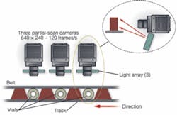
“In this particular application,” says Serra, “containers are indexed between pockets of a conveyor, three pieces at a time across the field of view of three partial-scan cameras from Toshiba Teli America. After moving into the field of view, the products are held there, and a belt located above the neck of each container spins each one to ensure that an image of the barcode location is captured by the camera (see Fig. 1). Under control of a PLC from Omron, this belt rotates each product approximately 1.5 times within 400 ms.

Three 25-mm2 LED arrays from NERLITE (also part of Siemens Energy and Automation) illuminate the containers as they rotate. These NERLITE red LED arrays are placed below each of the cameras and off-axis. “Using red LED illumination in such an application increases the contrast of the black barcode against the white background of the container, making automated inspection easier,” says Serra.
Partial scanning
“Because the 640 × 480-pixel CCD, 60-frames/s cameras are run in partial-scan mode,” says Serra, “640 × 240 images can be captured by each camera at a rate of 120 frames/s.” Such a high rate allows up to 50 images to be captured per camera within 400 ms. “However,” says Serra, “this results in more images than are required, and in the final system each camera is triggered 25 times resulting in a total of 25 images per camera or 75 images that need to be processed.”
RS-170 progressive-scan signals from each of the three CCD cameras are interfaced to a PC-based IPD VA40 Vision Appliance from DALSA for processing. “Because the VA40 provides multiple camera inputs,” says Serra, “inspection of different views of the same part or different parts can be accomplished simultaneously. To interface to the system’s PLC, the VA40 features industrial-grade inputs and outputs that are broken out to removable screw terminal connectors or optoisolation modules. The unit’s serial communication ports include RS-232, USB, and Ethernet for connecting into the factory network.
Running IPD Sherlock image-processing software allows the system to be configured to capture and analyze all 75 images as they are captured at 120 frames/s from the CCD cameras. “To ensure that a complete barcode image is captured, the system must analyze all 75 images before any barcode-reading tasks can be accomplished,” says Serra. To do this, the location of each barcode within these images must be properly determined.
Machine vision
As each set of 25 images is captured by each camera, an analysis tool within the Sherlock software finds the largest blob within the images. This blob-analysis tool performs 3 x 3 erosions three times that connect all the pixels within the Data Matrix code (see Fig. 2). Determining the largest blob within a set of images ensures that the most accurate image of the barcode is captured. Then, a connectivity algorithm is used to find the outer points of the blob.
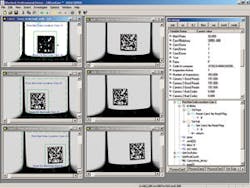
Using the data, the center point of the blob can be determined and used as a reference to position a region of interest (ROI) across the original image that has been stored in the VA40 system memory. “In this way,” says Serra, “the system locates the best possible image with which to perform barcode analysis.”
After the ROI is determined, a barcode reader tool, also within Sherlock, determines the product description, batch lot, and expiration date within the container. These data are then transferred to the system’s database-control system over Ethernet from the VA40 vision appliance. “By monitoring these data,” says Serra, “the company’s host database system can determine the status of each batch of containers and be used for predictive maintenance of the upstream labeling system.”
Get a GUI
Serra and his colleagues from CPU Automation coded the VA40 in Visual Basic to allow the operator to visualize the inspection process. The graphical user interface (GUI) displays images from all three cameras as they are captured in real time (see Fig. 3). “More important, however,” says Serra, “the GUI shows the number of good and bad reads as the system analyzes each of the containers. This lets the operator visualize how the system is performing the barcode-inspection function.”
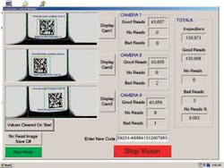
Should any part fail inspection, the VA40 transmits this information over its discrete I/O lines to the PLC. Further along the conveyor, a pick-and-place robot packs properly validated containers into cartons for shipping to pharmaceutical outlets and hospitals. Because the VA40 transmits the failed data to the PLC, the information can be used to disable the pick-and-place mechanism for individual cartons, ensuring they will not be packed for shipping.
For a total cost of $9000 including cameras, lighting, and the machine-vision system, the system has been running continuously in the company’s facility for more than a year. “In the future, more systems will be added as the company expands production,” says Serra. And, the DALSA IPD VA20 vision appliance has many of the features of the VA40, so the unit can be used in similar systems that may only require two cameras. “This would lower the typical system cost to around $5000.”

null