Graphical user interfaces ease programming
Andrew Wilson, Editor, [email protected]
A number of camera vendors are embedding image-processing functions within FPGAs to speed preprocessing tasks such as flat-field correction, filtering, and Bayer interpolation (see Vision Systems Design, May 2007, p. 49). At the upcoming VISION 2007 (Stuttgart, Germany; 6-8 November), smart-camera and software vendors will demonstrate another trend by showing how simple-to-use development tools can ease the tasks of embedding machine-vision functions into smart cameras and systems.
Rather than offer the system developer a series of C-callable routines, vendors are now beginning to incorporate graphical user interfaces into their software products. These tools allow a series of linear processing steps to be combined with conditional branching and looping functions so that automated systems can be built that perform processing steps based on characteristics found within the image.
Last year, for example, National Instruments (Austin, TX, USA; www.ni.com) showed how its Vision Builder for Automated Inspection (AI) uses a graphical state machine that incorporates more than 50 inspection steps in the Vision Builder AI graphical software library. Currently running on the NI Compact Vision System and frame grabbers, developers can use the library to read and write values and measurements to and from TTL and optoisolated digital lines (see Vision Systems Design, October 2006 p. 22).
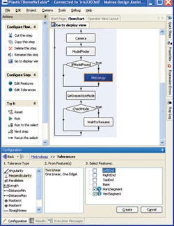
NI is not alone in recognizing the power of bringing graphical tools to developers. Recently, Matrox Imaging (Dorval, QC, Canada; www.matrox.com/imaging) demonstrated the latest version of its Design Assistant, an integrated design environment (IDE) that the company is offering for its Iris E-Series of smart cameras. As a graphical front end, the IDE uses a number of functions from the Matrox Imaging Library (MIL) that are represented as flow-chart steps. Supporting both image-calibration and part-localization functions, the Matrox software also incorporates machine-vision functions such as barcode reading, metrology, presence/absence detection, an edge locator, and geometric pattern-matching functions.
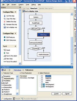
To produce a program using the Matrox IDE, the developer is presented with a workspace that includes the image captured by the E-Series camera. The workspace, called the configuration window, lets the user create a flow chart of the necessary image-processing functions, such as object localization or measuring. During deployment, the object would be measured according to the steps previously applied in the configuration window (see figure).
Results of these measurements are displayed in another window within the workspace. Pass/fail tools also can be linked to results or expressions computed by the vision algorithms and graphical overlays to show the types of measurements being performed. Once a specific pass/fail decision has been made, the software’s IOWriter user interface triggers the digital I/O lines of the E-Series camera. Alternatively, I/O functions can be transferred over the unit’s Ethernet or serial RS-232 interface.
According to Irene Leszkowicz, leader of the Interactive Imaging Products Group at Matrox, future enhancements for the Design Assistant software will include normalized gray-scale correlation, blob analysis, and text reading. As well, developers will be able to program the camera using the MIL.

