Seal of Approval

GigE cameras, vision computer, and LED lighting inspect auto airbag screw seals
Ben Dawson and Scott Montgomery, DALSA
First-tier automotive suppliers make subassemblies from parts provided by second-tier manufacturers. These subassemblies-for example, steering wheels-are inspected when received at the automotive assembly plant. Any defects found can cause a quality rejection (QR) of the entire lot of subassemblies, with corresponding financial penalties against the supplier. Even worse, workers will stop the assembly line if a defective part is found. In this case, there are substantial financial penalties for the supplier, often based on the time (to the minute) that the line is down and lost revenue for the automobile manufacturer.

Engineering Specialties, Inc. (ESI), a second-tier supplier, manufactures parts used in automotive safety systems. To avoid costly defects and meet part quality requirements for a small but critical water-sealed Torx screw assembly used in Jeep Wrangler airbag control systems, Carmen Ciardiello, ESI’s vice president and general manager, installed a vision-based inspection system.
Off-road toughness
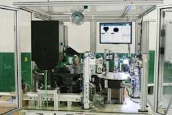
ESI’s Torx screws with water-tight green rubber seals help keep water out of airbag control systems when Jeep Wrangler owners decide to slog it off-road, making these screws an important component of a critical automotive safety system. “As people go four-wheeling off-road, the underside of the center console could get wet,” explains ESI’s Ciardiello. “Any water leaking into the box containing the airbag control system could cause the system to fail, with disastrous results. So the quality of the screw and seal is a major concern.” Process improvements could not meet customer quality requirements, so ESI built machine vision into the green seal machine (see Fig. 1).
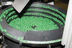
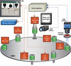
The green seal machine inserts a Torx screw into a green seal and uses two DALSA Genie cameras with telecentric lenses from Edmund Optics to inspect the screw/seal assembly. An operator loads two hoppers: one with seals, another with screws. These hoppers dispense into vibratory bowl feeders that singulate the parts (see Fig. 2). A blind mechanical slide end effector moves over a green seal, picks it up, and sets it in a nest in a circular index table. The control PLC and mechanics, designed and built by CMS Automation, then index the table to the next station where a Torx screw is partially inserted into the green seal (see Fig. 3).
The table indexes again to the first of two vision inspection stations. At this station, a linear slide lowers a hood with a Torx screwdriver over the screw head and a second linear slide pushes the screw/seal upward and into the view of a horizontally mounted DALSA Genie Gigabit Ethernet (GigE) camera. The seal and screw are then rotated to acquire side-view images of them. Although this system does not require the speed of GigE, prudent planning for future speed increases and relative equipment costs suggested that the new Genie cameras were the best solution.
Image capture
Both DALSA cameras used for side and top inspection of the screw/seal assembly are connected via GigE to a DALSA IPD VA61 Vision Appliance, essentially a compact computer with eight digital I/Os, two analog trigger I/Os for trigger signals, two GigE ports, and an RS-232 serial port, which is connected to the PLC running the index table and other mechanisms.
After the screw/seal is pushed upward, the PLC rotates the screw/seal in eight steps over 540° and signals the VA61 to acquire an image at each step. A Siemens white LED panel light provides even, bright illumination of the screw/seal assembly (see Fig. 4), while a sanded piece of metal placed on the opposite side of the assembly from the camera provides a uniform gray background for the image to enhance contrast at the edges of the screw and seal.

As each acquired image is fed to the VA61, DALSA IPD’s Sherlock image-processing software uses edge-detection algorithms to isolate the edge of the screw and seal (see Fig. 5). A caliper tool verifies the screw diameter at the threads and at the tapered shoulder just below the screw head and the diameters of the ribs on the green seal. A thread tool then measures the peak-to-peak distance between threads on the screw to check the screw quality. The caliper tool also verifies that the screw has been pushed far enough into the seal by measuring the distance between the top of the Torx screw and the top of the green seal. To meet a quality specification, compressed air blows away loose contaminants.
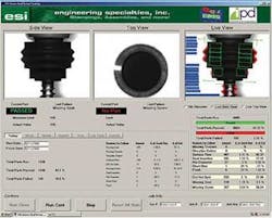
Finally, the software searches for intensity variations in 12 regions of interest set on the sides of the seal. The ROIs are located on the edges of the seal because as the perimeter of the circular seal naturally turns away from the camera, the reflected light improves defect contrast within the seal itself. Sherlock searches within each ROI for intensity variations indicative of foreign material or voids from a “short shot” on the surface of the seal itself.
From the top down
If values from all the inspection routines are within preset limits, the vision system sends a signal back to the PLC telling it the inspection passed or failed. The PLC stores the information for that screw assembly/table position, lowers the screw back to the nest, and indexes the table. Another linear slide is activated at Station 4, which applies additional pressure to the screw in the seal, pushing the screw down to make the green seal come up over the top edge of the Torx screw.
The PLC indexes the table again, and triggers the VA61 to perform the second inspection (while at the same time inspecting a new screw at Station 3). This time, a Genie camera is mounted directly above the screw with a red LED ringlight from Advanced Illumination. Red light is used at this station to improve the contrast between the green seal and everything else, while Station 3 uses white light to highlight both the seal and the screw.
The Sherlock software analyzes the top image using a radial caliper tool to make 40 measurements from the center of the screw to the outside of the seal. If the screw has been properly inserted and pressed into the seal, then the green seal will come up and over the top of the screw to form a water-tight seal. If the screw is not properly inserted, the seal will be distorted and the radial caliper measures will show this. Any distortions could cause the seal to leak. If the screw is missing, the center area will be black and the part is rejected. The VA61 sends the pass/fail information to the PLC, saves the two inspection results to its internal hard drive, and records images of failed parts for review.
The PLC indexes the table again, to the reject station where a linear slide with a vacuum cup removes defective or incomplete screw/seal assemblies. The table indexes again to the accept station, and another slide and vacuum cup put inspected assemblies into a conveyer to an accept bin.
The VA61’s Ethernet interface also connects to ESI’s LAN. Should the PLC register an empty bin or several screw assemblies fail in a row, an e-mail alarm is automatically generated by the VA61 and sent to the machine’s operator via mobile phone or device, telling the operator that the workstation needs attention.
ESI manufactures and inspects approximately 40,000 of these parts per week, or more than 2 million of these parts per year. Ciardiello describes some of the finance issues of using machine vision in automotive part inspection. “The vision system is petty cash in comparison to the financial penalties that can be levied on the tier suppliers. I’ve heard of penalties as high as $1,000 a minute for quality issues that stop a production line, but I think something like $50,000 penalty per shift is more common. As a result of using machine vision, our quality rating is now number one out of 38 vendors in our second-tier supplier category.”
Ben Dawson is director, strategic development, and Scott Montgomery is senior applications engineer at DALSA, Billerica, MA, USA; www.dalsa.com.
Company Info
Advanced Illumination
Rochester, VT, USA
www.advancedillumination.com
CMS Automation
Waterbury, CT, USA
www.cmsautomationinc.com
DALSA
Billerica, MA, USA
www.dalsa.com
Edmund Optics
Barrington, NJ, USA
www.edmundoptics.com
Engineering Specialties
North Branford, CT, USA
www.esict.com
Siemens Energy & Automation
Nashua, NH, USA
www.nerlite.com