By Andrew Wilson
Six years ago, PVI Systems (Niantic, CT, USA; www.pvisys.com) introduced a semi-automated machine-vision system that can be used to test various ST, SC, SMA, D4, and MT type fiberoptic connectors. Dubbed the Fiber QA-EFI, the end-face inspection system digitizes images from a number of off-the-shelf fiber microscopes to analyze captured fiber images for scratches, cracks, and chips (see “System examines fiberoptic assemblies,”Vision Systems Design, July 2002, pp. 24-29).
Two years later, the company developed a more sophisticated system, known as the FiberQA-AVIT that can inspect several hundred fibers in high-density MT connectors, as well as single-fiber SC and FC connectors. The system was a natural extension of the FiberQA system, adding motion control and automated focusing to eliminate operator interaction, except for loading and unloading of parts to be tested (see “Machine-vision system inspects fiber connectors,” Vision Systems Design, October 2003, pp. 59-62).
“While Fiber QA-EFI was developed for testing single-fiber connectors,” says Douglas Wilson, president of PVI Systems, “the FiberQA-AVIT system was developed for manufacturers of single-board switches and routers that use multiple fiberoptic-based connectors that have many rows of multiple card edge connectors that each integrate hundreds of optical fibers. Companies that produce single fiberoptic connectors, however, also require multiple connectors to be analyzed after the fibers are mounted and polished within a variety of single-fiber connectors such as LC or SC.”
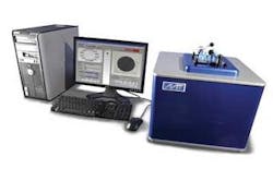
To meet these demands, PVI Systems has re-engineered its FiberQA-AVIT system, introducing the mini-AVIT, a desktop fiber-connector inspection system designed specifically to allow multiple single-fiber connectors to be analyzed automatically (see Fig. 1). The system is designed to accommodate a number of different polishing plates or custom fixtures or containing multiple connectors. The mini-AVIT system also inspects multifiber MT-type connectors within polishing plates.
Like its big brother, the Fiber-QA AVIT system, the mini-AVIT uses a number of off-the-shelf components including lenses, x-y-z stages, cameras, frame grabbers, and motion controllers mounted in a custom enclosure and fixture receiver.
“Because the location of each fiber must be determined to within ±15 µm,” says Wilson, “it is first necessary to roughly determine the position of each ferrule and then to more accurately measure the fiber location within the connector.” To accomplish this, Wilson and his colleagues developed a dual camera-based system mounted on an x-y-z stage, custom built for PVI by Del-Tron Precision (Bethel, CT, USA; www.deltron.com).
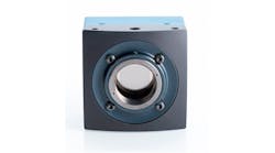
To determine the position of the ferrule, the x-y-z stage is programmed to a preset location on the fixture using a PC-based NI 7344 stepper controller board from National Instruments (Austin, TX, USA; www.ni.com) that is interfaced to a Universal Motion Interface also from NI. Using a 648 × 488 Dragonfly2 board-level camera from Point Grey Research (Richmond, BC, Canada; www.ptgrey.com) with a 94-mm lens from Infinity Photo-Optical (Boulder, CO, USA; www.infinity-usa.com) mounted on the stage, a field of view (FOV) larger than the ferrule is imaged. Mounted on the x-y-z stage, images from the FireWire-based Dragonfly2 camera are then transferred to the host PC using a low-cost 1394b interface board.
“After the system determines the location of the ferrule and the individual fiber accurately enough, a high-magnification camera system, also mounted on the x-y-z stage, is used to image the individual fiber within the connector,” says Wilson. This imaging task is also performed using a 648 × 488 Dragonfly2 board-level camera mounted with a Precise Eye lens assembly from Navitar (Rochester, NY, USA; www.navitar.com) that is coupled to a 10X objective from Mitutoyo America (Aurora, IL, USA; www.mitutoyo.com). Images from this camera are also transferred to the host PC using the same 1394b PC interface board.
A DOAL-25 coaxial (on axis) white light LED illuminator from Siemens (Nashua, NH, USA; www.nerlite.com) is used to provide uniform illumination across the highly reflective ferrule surfaces. “With this coaxial lighting approach,” says Wilson, “the specular surfaces of the ferrule appear illuminated, while non-specular surfaces reflect the light outside the acceptance cone of the lens and appear dark.” A custom blue single LED is used to improve the resolution of the high-magnification fiber camera system, through a beamsplitter integral to the Precise Eye lens assembly. Special preparation of this LED improves the lighting uniformity-important to detection of low-contrast defects-while maintaining high light output.
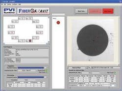
To move the x-y-z stage and analyze captured images for scratches, cracks, and chips, PVI Systems used NI LabVIEW software with the NI Motion and NI Vision Development Modules. Developing the user interface was also accomplished using LabVIEW and resembles the interface used in the company’s Fiber-QA-EFI system, except that as single fibers are analyzed, they are presented to the operator and the results of the multiple operations displayed on the interface (see Fig. 2).
At this year’s NIWeek, PVI Systems showed the first version of the mini-AVIT system inspecting 12 single fiberoptic connectors. According to Wilson, the system can automatically analyze all 12 fibers for scratches and contamination and present statistical data to the operator in less than 3 minutes. “Because this is far less than the time taken to polish 12 connectors, fiber connector manufacturers now have a means to increase production throughput while reducing costs.”
