Digital wavefront sensors bring accuracy in optical product quality

Optical products such as aspheric lenses widely used in mobile phones or microlenses for DVD pickup heads are produced in increasing quantities; mass production is now achieved with large numbers of micro-optical elements on single wafers. Optical elements have more and more complex wavefront shapes to reduce the number of individual elements and to improve final assembly performances and cost.
As a result, there is a growing demand from micro-optical manufacturers for higher dynamic and spatial resolution inspection systems to ensure quality production. These systems can be used for in-line testing with high throughput.
Interferometry has been the leading technology in this field, but its use on the shop floor has been limited because it is sensitive to vibration. Consequently, new optical inspection systems have been emerging on the marketplace, offering higher dynamic range and fast measurement in production environments—these include Shack-Hartman sensors, lateral shearing interferometers, or curvature sensors-based systems. These so-called wavefront sensors use an array of small lenses or diffractive elements that focus the optical wavefront onto a sensor.
In the Shack-Hartmann sensor, the position of these spots produces a regular symmetric grid since the incoming wavefront is a plane. As this wavefront becomes distorted, the spots are displaced. Since this displacement is directly related to the incoming wavefront, which is directly related to the surface profile of the object being imaged, the wavefront slopes across the array and the surface profile of the imaged object can be calculated.
One variation of Shack-Hartman interferometer—the lateral shearing interferometer—uses a 2-D diffraction grating to split the incident light into several sub-beams that interfere at the sensor plane. Like Shack-Hartman and lateral shearing interferometers, curvature sensors can also be used to measure the 3-D profile of objects such as contact lenses and wafers or used for laser beam analysis. In these sensors, the 2-D diffraction grating of the lateral shearing interferometer is replaced with a parabolic-shaped diffraction grating with spatially varying period and pitch.
To reduce the number of components used in these systems, PhaseView (Palaiseau, France;www.phaseview.net) has introduced what the company calls a digital wavefront sensor. According to Igor Lyuboshenko, CEO, this digital wavefront sensor reduces the number of hardware components such as diffraction gratings and microlenses while employing specialized algorithms to reconstruct the wavefront profile.
“Digital wavefront sensors rely upon measurements of the energy redistribution in 3-D space,” says Lyuboshenko. “Similar to curvature sensors, they measure the variation of the wave’s intensity on the optical axis and also, like Shack-Hartman and lateral shearing interferometers, they also measure the redistribution of the wave’s intensity in the transverse (x, y) direction”.
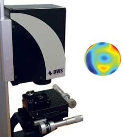
This measurement of intensity in three dimensions leads to a high-resolution reconstruction of the wavefront without using diffracting elements or microlenses at the cost of increased computational expense. This is accomplished by capturing the intensity of a number of different images and applying complex differential equation solvers to compute the wavefront profile. Incorporated into PhaseView’s latest Digital Wavefront Sensor (DWS), this technology allows the system to capture images at 25 frames/s and generate 3-D profiles at 15 frames/s. With a resolution of 250,000 measurement points across a 5-mm aperture, the sensor can operate over a 350–1100-nm spectrum (see figure).
“With no specialized hardware elements, the camera can operate from wavelengths ranging from UV to x-ray measuring wavefront tilt, divergence, and convergence, making it especially suitable in applications such as laser and optics characterization, and eye measurements like thin-retina nerve terminations in patients with glaucoma,” says Lyuboshenko. For aspherics inspection, for example, the company’s WaveGauge system, also based on DWS technology, can measure 5-mm aperture lenses with 250,000 measurement points, repeatability RMS of /1000, and absolute accuracy of /100.
Vision-guided robots speed sheet metal cutting
Positioning accuracy is critical when using robot-assisted systems to fabricate large irregular sheets of metal. In many cases, these metal sheets are large and heavy but still need to be positioned accurately before cutting can commence. Since robot-assisted cutting systems operate in a preprogrammed fashion, the edges of these sheets must be presented to such systems in a perfectly aligned fashion so that any cuts are accurately formed.
To meet these requirements, Severt Robotertechnik (Vreden, Germany;www.severt-gmbh.de), a systems supplier of robotic systems for the automotive industry, called on Sensor Control (Västerås, Sweden; www.sensorcontrol.com) to provide a vision-guided robotic system. According to Robert Hogarth of Sensor Control, the system was required to decrease the production time required to fabricate cut sheet metal parts as well as lower any possible rework costs.

To accomplish this, Sensor Control developed a specialized workcell that consisted of 10 HR70 monochrome CCD cameras from Sony (Park Ridge, NJ, USA; www.sony.com/videocameras) mounted in the ceiling above the robot station and interfaced to a PC using a number of frame grabbers from Matrox (Dorval, QC, Canada; www.matrox.com/imaging). These ceiling-based cameras image the metal sheet that is located on a positioning table in the workcell (see figure).
To identify both the position and dimensions of the metal sheet, the PC-based system uses an application-specific version of Sensor Controls’ OptiMaster II PathAdjuster 3D vision/control system. Developed using Matrox’s MIL imaging library and Microsoft’s Visual Studio, the software first combines multiple images from the ceiling cameras. The position coordinates of the metal sheet on the workcell table are then calculated and transmitted over an RS-232 interface to a six-axis robot from ABB (Zurich, Switzerland;www.abb.com).
Should the metal sheet be less than 0.8 × 1 m, one of two cameras on the robot’s end effector is used instead of the fixed ceiling cameras for accurate sheet orientation. “Even though calibration software resides in the OptiMaster system, this calibration routine can also be performed using the ABB robot’s teach-pendant,” says Hogarth.
Using these coordinates, the original blueprint measurements of the metal sheet to be fabricated are then compared with the measured position coordinates of the sheet metal within the workcell and the robot cutting path adjusted for the sheet’s correct position on the table. For a sheet size of 1.2 × 9.5 m, this correction takes approximately 90 s.
After the positioning of the sheet metal is known, a structured laser light from StockerYale (Montreal, QC, Canada;www.stockeryale.com) located on the end of the robotic arm scans the surface for critical holes and key features on the metal. Reflected laser light is then captured by another HR70 camera and the data placed in host PC memory. Once this data is downloaded, the camera is detached from the robot’s end effector before cutting commences.
“In these applications, the focal length of the lenses used depends upon the robot’s working envelope and the resolution required,” says Hogarth. “In this case 8-, 12-, and 16 mm lenses were used to provide object-to-camera distances from 20 mm to 5 m. For the camera used to image data from the structured laser light, a bandpass filter was used to block frequencies other than the 670-nm red laser frequency.”
Because all Sensor Control machine-vision systems use PCs as host controllers, the system can be connected to the user’s network to allow remote production control and remote connection to technical support, if required.
“In operation, unfinished square, circular, oval, and asymmetrical metal sheets can now be placed on the table within the workcell without any specific placement requirements,” says Hogarth. “Without operator intervention, the system can then fabricate the part to meet the specific requirements detailed in the customer’s blueprint.”