Technical Color
High-resolution linescan cameras use multichip designs and prisms to improve color fidelity
Although many machine-vision applications use low-cost monochrome cameras to perform simple parts-presence applications, other more sophisticated applications such as high-speed fruit sorting and web inspection demand the use of color. To meet this demand, camera vendors offer a variety of color linescan cameras with discrete or multiple image sensors to perform the task.
In the simplest linescan cameras, a single detector captures a color image. Because all of these sensors are essentially monochromatic, a mosaic filter pattern is arranged over the imager. In the design of linear detectors used in linescan cameras, this pattern may be of a simple RGB format repeated across the length of the device. Such methods trade off resolution for cost, since while each, say 5-µm pixel, may return an R, G, or B color value, the true color value can only be obtained by using data from all three pixels.

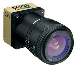
In the design of its AViiVA SC2 camera, for example, e2v uses a 4k × 1-pixel color sensor with 10-µm pixel size and an RGB color pattern (1365 × RGB pattern). Designed for low-cost image capture, the camera supports both Camera Link and LVDS interfaces and features on-board flat-field correction and color space correction (see Fig. 1).
Filter patterns
Filter mosaics can also be implemented in other ways—most notably using the Bayer color mosaic—to render a color image that more closely mimics the human eye’s resolving power. In this approach, a color filter array is arranged over the imager with half the pixels filtered as green, 25% red, and 25% blue. By interpolating the color information from surrounding pixels, RGB color data for each pixel can be calculated. Because this interpolation process is inherently parallel, it can easily be performed using an FPGA in the camera. However, because the RGB values for each pixel are interpolated, RGB color information produced by these cameras only represents an approximate value for the color at each point on the image.
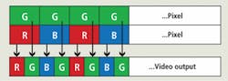
Sensors that use the Bayer pattern to capture color images are most often area-array-based, such as those offered by Kodak and Sony, although variations of the technology have appeared in some bilinear linescan cameras, most notably the SK 4096 DJRC from Schäfter + Kirchhoff. In this so-called bilinear design, the CCD sensor of the camera has two closely spaced parallel sensor arrays with 2048 pixels each. While the pixels of the upper array are covered with green filters, the pixels of the lower array are covered alternately with red and with blue filters. Digital data are then output in RGBG RGBG format (see Fig. 2).
Of course, bilinear linescan camera designs do not require the camera’s image sensor to be monolithic. Princeton Lightwave has developed a dual-band linescan camera that uses two independent sensors optically coupled to allow simultaneous imaging in both the visible (400–900 nm) and infrared (1000–1700 nm) wavelengths. While visible sensing is provided by a 2k × 1 CCD, IR is detected by a 512 × 1-element InGaAs array. Each sensor provides two analog output streams that are processed using correlated double sampling, dark-level correction, and analog gain. Finally, the streams are converted to 12-bit digital data and output as two independent Camera Link interfaces.
Sensor designs
Vendors are also using sensor designs to implement their linescan color-camera designs. These take the form of trilinear and quadrilinear sensors that use different sensor architectures to capture color images. Linescan cameras incorporating monolithic trilinear sensors consist of three parallel linear CCD elements that are also separately coated with RGB filters.
In its latest ruL2098-10gc, a GigE Vision linescan camera, for example, Basler Vision Technologies incorporates a trilinear sensor with three separate light-sensitive lines to collect red, green, and blue image data. A built-in spatial correction capability can be used to compensate for the space between each sensor line (see Fig. 3).

Taking this approach one step further, some camera vendors offer quadrilinear devices that add a fourth parallel channel to the three parallel linear R, G, and B signals used for color image capture. This channel can be used for luminance information (Y) or near-infrared (near-IR) channel. Adding this extra near-IR channel allows cameras based on these devices to be targeted toward multispectral applications such as food sorting and the film/document scanning.
In the design of its EliiXA linescan camera series, for example, e2v offers both trilinear and quadrilinear CCD imagers of 4k × 3 or 4k × 4 running at 18 kHz. While the trilinear version produces RGB output, the company also offers two quadrilinear versions with either RGB or monochrome channels or with an RGB and near-IR channels. Each camera will be available at a full pixel clock rate of 320 MHz or half pixel rate. Both versions will feature a Camera Link interfaces.
Because bi-, tri-, and quadrilinear sensors scan the RG, B, RGB, or RGBY “colors” in different physical planes, it is important to minimize the distance between the rows of the RG, B, RGB, or RGBY linear sensing elements to reduce any image artifacts that may occur when the sensor is used in high-speed applications. In these applications, the surface of an object may not be perpendicular to the camera, and even a slight rotation of the camera may cause improper color registration. Thus, when designing bi-, tri-, or quadrilinear sensors, IC designers strive to keep the spacing between linear elements as low as possible. The e2v EliiXA series uses 10-µm spacing between each row of monolithic CCD imagers, a figure that the company claims is the lowest of any linescan camera available.
High-fidelity color
While most color machine-vision applications use color cameras with mosaic or filtered image photosites to capture color objects, some high-speed industrial applications require higher-fidelity color capture. Today, the most popular way to improve the quality of color capture is the use of prism-based cameras.
Using a prism to split white light into three RGB spectral components, these cameras employ three separate CCD or CMOS devices abutted to the faces of the prism. Because of this, the imagers in these cameras require no mosaic filter so that once properly registered, a more accurate color image rendition can be obtained.
Of course, the use of multiple imagers increases the cost of the cameras. And, because the prism block distances the image plane of the imagers and the back of the camera lens, more complex and costly lenses are required. Despite this, many camera manufacturers are using this technology in their linescan camera designs.
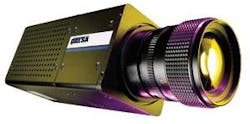
The Trillium color linescan cameras from Dalsa, for example, use a beam-splitting prism, interference filters, and three separate image sensors to provide separate outputs from a common optical axis (see Fig. 4). LVDS output of all three 1k × 1 or 2k × 1 RGB channels can be adjusted to provide programmable pixel-by-pixel color correction and self-calibration.
TVI Vision also offers a range of linescan cameras based on this technology in its XIIMUS range. These cameras use R, G, B linear arrays of 3 × 512, 1024, or 2048 pixels with maximum data rates of up 65,000 lines/s. Not only do such cameras allow high-fidelity color images to be captured, they can also be used in multispectral applications. As well as offering R, G, and B configurations, for example, XIIMUS cameras can also be supplied with R, GB and IR sensors.
TVI Vision is not the only linescan company to realize the potential of multispectral linescan cameras. In April 2008, for example, JAI announced it would offer a linescan camera developed for such applications (see www.vision-systems.com/articles/324721/). According to Steve Kinney, JAI director of technical presales and support, JAI’s linescan camera will use three 19-kHz linescan CCD imagers filtered as blue-green, red, and near-IR. This will be especially useful for applications such as food inspection, where color images must be simultaneously processed with near-IR images.
While today’s color linescan cameras use several different sensor architectures to capture color images, each one has specific price/performance trade-offs. At one end of the spectrum, single linear linescan cameras remain the most cost-effective, while applications demanding greater color fidelity mandate the use of more-expensive prism-based cameras. And, because color linescan cameras are more expensive than color area-array cameras, there are fewer sensor and camera vendors, leaving the system integrator fewer choices when deciding on which type of color linescan camera to purchase.

Prism cameras look for HD-SDI support
Before the advent of digital camera interfaces such as USB, FireWire, GigE, and Camera Link, most machine-vision systems relied on cameras with analog output. Based on broadcast standards such as RS-170 and NTSC, these analog color cameras provided low-cost solutions to system integrators, since the components used in their designs were mass-produced by semiconductor vendors keen on supplying parts to high-volume broadcast TV manufacturers.
Now, with the advent of high-definition video and high-resolution area-array prism-based color cameras, many Japanese cameras are again endorsing broadcast standards, this time in the form of the high-definition serial digital interface (HD-SDI), a standard ratified by the Society of Motion Picture and Television Engineers (SMPTE) as SMPTE 292M. Providing a nominal data rate of 1.485 Gbit/s, the standard has become widely accepted in the broadcast industry, spawning faster versions that consist of a pair of SMPTE 292M links running at 2.970 Gbits/s known as SMPTE 372M and a more recent interface consisting of a single 2.97-Gbit/s serial link known as SMPTE 424M.
To date, a number of companies including Iconix, Hitachi Kokusai Electric America, Panasonic Vision Systems, Sony, and Toshiba America have introduced area-array based prism color cameras that incorporate the HD-SDI interface. While many of these use remote camera heads and tethered camera control boxes to adjust camera parameters, other provide single-head cameras with HD-SDI output.
Hitachi’s HV-HD30 HDTV digital color camera, for example, incorporates three HDTV 1/3-in 1.3M CMOS sensors and an HD-SDI output. Camera adjustments can be made either remotely using the company’s remote-control unit or directly from a PC. In the design of its HDC-X310, Sony’s prism-based camera uses three 1/2-in., 1.5-Mpixel CCDs in a single-camera housing. The HDC-X310 features 1440 × 1080 full-color pixels and optional interface boards that provide HD-SDI output.

Costing approximately $10,000, these cameras are now finding uses in medical imaging applications such as ophthalmology, where perfectly registered, high-resolution color images are demanded. To develop systems based around these cameras, integrators are looking to conventional machine-vision frame-grabber vendors for help. While several of these are currently under development, Active Silicon is the first company to demonstrate such a product (see figure).
Known as the Phoenix HDI-SDI range, the D20HDSDI frame grabber allows both SDI and HD-SDI inputs to be captured, while the entry-level D10HDSDI has single-channel capability. While the D10HDSDI is offered as a single 1x lane PCI Express board, the D20HDSDI offers a 4x lane interface that supports bandwidths in excess of 750 Mbytes/s. Both variants support the SMPTE 292M standard. “At present,” says Colin Pearce, managing director of Active Silicon, “the market demand for this board appears to be with Toshiba’s IK-HD1 HDTV and Panasonic’s GP-US932HT cameras that both offer HD-SDI output.”