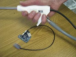
Disposable scopes eliminate infection
According to the US Centers for Disease Control and Prevention (Atlanta, GA, USA; www.cdc.gov), reusable medical devices such as endoscopes and arthroscopes should be sterilized before each use. Sterilization processes include moist heat by steam autoclaving, use of ethylene oxide gas, dry heat, or use of chemical germicides designed to destroy any microbes that may be present. Despite the rigorous standards governing sterilization, one recent poll of health-care professionals in England found that 5% did not clean their instruments between patient exams, and greater than 50% reused the sterilizing fluid after each exam!
Realizing this, Jeffrey Adair, founder and vice president of research and development of Micro-Imaging Solutions (MIS; Englewood, CO, USA; www.micro-imaging.us) set out to design low-cost medical-imaging products that once used could be discarded, eliminating any need for sterilization. The company’s first product, currently under development, is a fiberoptic scope, or arthroscope, that is placed by a physician into a joint space through a small incision to perform both diagnostic and treatment within the joint.
“With the advent of small, low-cost CMOS imagers, applications in less-invasive surgical procedures become clear,” says Adair. Because these CMOS color imagers cost about 1/20 the price of a CCD, they can be used in low-cost surgical instruments.” To build the first prototype of its digital disposable arthroscope, Adair and his colleagues turned to Imaging Solutions Group (ISG; Fairport, NY, USA; www.isgchips.com).
“Products such as arthroscopes generally use xenon-lamp-based fiberoptic light sources that are coupled to the probe,” says Kerry Van Iseghem, cofounder of ISG. “This provides the necessary illumination to allow a CCD- or CMOS-based imager placed at the end of the probe to digitize an image of the joint.”
In the design of the MIS arthroscope, it was necessary to reduce the cost of the probe by using a 1/10-in., 1.3-Mpixel, 8-bit CMOS color imager that was custom-built by Cypress Semiconductor (San Jose, CA, USA; www.cypress.com). The use of a CMOS imager reduced the amount of power that needed to be delivered to the imager, simplified the clocking signals required, and allowed 3.3-V analog images to be transmitted directly to the handle of the arthroscope. Here, the signals were amplified to maintain a 3.3-V analog signal and then digitized (see Fig. 1).
Rather than use standard camera interfaces such as FireWire or USB to transmit image data from the probe handle to the arthroscope controller, ISG opted to use the high-definition multimedia interface—HDMI (www.hdmi.org). Like Camera Link, the HDMI cable uses a number of transition-minimized differential signaling (TMDS) differential pairs to transmit data. These channels carry video, audio, and auxiliary data. In the HDMI implementation, four differential pairs are used and audio, video, and auxiliary data are transmitted across three TMDS data channels. A TMDS clock, typically running at the video pixel rate, is transmitted on the TMDS clock channel.
“Since the HDMI supports data rates of 340 Mpixels/s, it is fast enough to support image transfer of 8-Mbit images at 30 frames/s,” says Van Iseghem. “Furthermore, because such chipsets are now being used by more than 600 companies in consumer-electronics products, the cost of the interface is lower than any other camera interface currently available.”
After images are transferred over approximately 2 m of HDMI cable to the arthroscope controller, they are processed by an embedded computer (see Fig. 2). This consists of a baseboard that allows the unit to output a variety of video formats such as VGA, NTSC, Ethernet, and S-Video, a stack of three boards used for I/O, CPU control, and an FPGA board to process image data in real time.
Under CPU control, functions such as Bayer color-space conversion, image rotation, hot pixel correction, and compression are performed at 30 frames/s and output in either VGA, NTSC, or S-Video format. “With the option of image compression, images can also be transmitted over Ethernet links so that the unit can be used as a telemedicine unit to transmit images to other medical personnel at different locations,” says Van Iseghem.


