An Illuminating Profile
Lens illumination profiles take on greater significance as machine-vision systems demand faster, clearer images
The recent increase in the use of machine vision has placed severe demands on the design of optical components. In addition, increases in sensor size and resolution have expanded the capabilities of machine-vision systems. The specifications of these sensors can often exceed the performance of standard optical components.
In designing and selecting optical components for machine-vision systems, factors to consider include working distance, field of view, cost, availability, and resolution. However, demands for higher resolution and speed are placing emphasis on a less-well-known aspect of optical components—the illumination profile. This illumination profile provides a map of the intensity of light across the entire field of view of the lens. In demanding applications, where light must be uniformly distributed, any deviation from a flat profile can have a significant effect on the system’s image quality.
Lenses that exhibit such deviations from a flat illumination profile can be corrected on the sensor itself or using the software supplied by the camera manufacturer (see Vision Systems Design, July 2006, p. 17). This process, called flat-field correction, uses an image of an evenly illuminated uniform object to determine the lens illumination profile, which becomes a reference to change the profile of individual pixels for each subsequent image. While this is a good solution for some applications, any subsequent adjustments to the aperture setting (F#) need to be compensated. Also, since this process adjusts system gain, it introduces potentially unwanted noise.
While flat-field correction can be used in many cameras systems, it can be more effective to overcome the profile problem optically. In many cases a lens design that corrects the issue provides better image quality across the entire image.
Numerous factors contribute to the illumination profile specification of a lens, including the sensor size, vignetting, rolloff, and F#. Understanding each one helps designers make the best decision when selecting a camera and lens for a particular application.
Sensors and vignetting
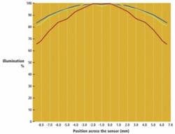
The ability of a lens to support certain sensor sizes is specified as its maximum format. If the imager is too large for the lens, the resulting image may appear to fade and degrade or even cut off toward the edges due to vignetting (see Fig. 1). This is an effect caused by the extinction of rays passing through the outer edges of the lens and illumination rolloff.

Although smaller imagers generally do not suffer from these problems, vignetting is still lens-dependent. In some applications outside of machine vision, compensation for vignetting is not critical. However, this effect in machine-vision systems can pose significant problems when parts need to be uniformly lit and corresponding uniform images captured.
Imaging of fine details is generally more difficult to reproduce at the edge of the image than at the center. This is because the rays that create the image at the edge are harder to control than those in the center. One way to manage this is to eliminate them from the system. Vignetting can remove the rays that are hardest to correct, thus making details at the edge of the image more defined (see Fig. 2).
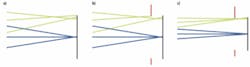
Adverse effects from manufacturing tolerances are also reflected in all areas of the image but become more pronounced at the edges. The looser the tolerances, the more adverse the effects can become; the tighter the tolerance, the higher the costs. Often a balance must be struck between reducing manufacturing cost and maintaining image quality, but because cost often becomes the main driver, vignetting must be used to maintain resolution across the field of view. This has an adverse effect on the illumination profile.
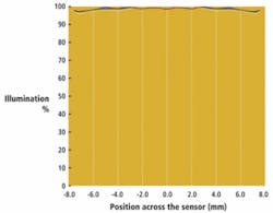
Conversely, lenses that have tighter tolerances generally yield a better overall image across the entire field of view. Another benefit of tighter tolerances is that repeatability from lens to lens is better, since there is far less variation unit to unit due to tolerances. Simply put, tighter tolerances produce better image quality and better illumination profiles. An added bonus of tighter tolerances is that larger sensors formats can be covered since higher image quality can be maintained further from the center of the field of view (see Fig. 3).
F# and rolloff
F#, the ratio of the focal length of an optical system to its clear aperture, also has a direct impact on the amount of vignetting in a lens. Minor vignetting effects can occur at F# settings lower than f/2.8. In addition, vignetting will generally increase as F# drops, for example, there will be more vignetting at f/1.4 than at f/2.8. Even the best lenses have difficulty not having larger amounts of vignetting in lenses with focal lengths of 16 mm and shorter than with apertures of f/2.0 and larger.
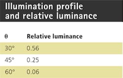
Rolloff is the relative difference between the amount of light reaching the image center and edges without vignetting. It is determined by calculating cos4, the angle between the chief ray at the center of the image and a ray at the edge of the image (see Fig. 4).
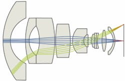
In many applications, rolloff is not an issue, but it can be problematic when increases. Increasing the angle between the chief ray and the ray at the edge of the image reduces the relative luminance at the edges of the image (see table).
This is especially true in linescan applications, where systems can be light starved due to short exposure times of the image sensor. Rolloff must also be considered in applications with short working distances and large fields of view. This can produce large values, regardless of sensor size.
One way to correct for rolloff is to design the lens to be image space telecentric, which eliminates and produces even illumination. Another way to offset rolloff is to create unbalanced illumination on the object under inspection. By mounting additional lights closer to the edges of the object under inspection or by adding neutral-density filters in front of the light source, rolloff can be reduced.
While appearing to be a minor issue, illumination profile can have a dramatic impact on the performance of a machine-vision system. Lenses with better illumination profiles generally provide better image quality and resolution.
Greg Hollows is director, machine vision solutions, Edmund Optics, Barrington, NJ, USA; www.edmundoptics.com.