Through the Automotive Glass
Robotic workcell uses machine vision, UV lighting, and filters to check the edge of automotive glass panels for proper application of primer
Variation Reduction Solutions (VRSI), which has been in the machine-vision-integration business for more than 10 years, was approached by a major automotive company to create an inspection system that would detect the presence or integrity of a very-fast-drying ultraviolet (UV) doped primer being applied to the edge of a 3 × 4-ft glass surface. Quinten Geyer and Arnold Berlin of VSRI took on this challenge with the support of Andrew Reed, sales engineer, and Dave Girouard, application engineer, of the McNaughton-McKay Electric Company—The Vision & Traceability Group, which provides distribution and support of machine-vision products.
The resulting inspection station is an in-line application with a relatively low production rate by automotive standards. However, there were two things the automotive company wanted the vision inspection station to achieve: detection of the presence or absence of primer on the edge of the glass panel and confirmation that the primer was applied evenly without any brakes or skips on the edge.
Inspection cell
The primer inspection system is part of a robotic cell that grips, checks, urethanes, and decks the glass panels for installation. The operator begins by applying primer to the edges of the glass panel. The panel is manually placed into a pickup tray where a KUKA six-axis robot grips the panel and presents it to the inspection system.
Because of space limitations, only half of the panel could be inspected at one time. To compensate, the robot was programmed to rotate the panel for the second inspection, presenting two different inspection orientations to the camera and light arrangement. After the inspection is complete, the robotic process then applies a layer of urethane. From there, the panel is decked and ready for installation in a vehicle.
VSRI chose a Cognex DVT 554 high-resolution camera and Intellect software with a custom VRSI script and a Tamron 23FM08 lens with Midwest Optics BP470 filter. The camera was networked to a cell PC using TCP/IP Ethernet for programming and image saving and a 24-Vdc discrete I/O interface to control the inspection process.
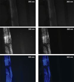
VRSI experimented in its lab with different lighting options. It found that using a machine-vision camera with a monochrome CCD array, the correct software, and tools that use ultraviolet (UV) lighting in a linear array illuminated the primer fairly well. The most significant challenge was getting enough UV light intensity to make the primer fluoresce brightly enough to achieve a reliable, clear image (see “UV 395 or 365”).
VRSI contacted Smart Vision Lights for assistance. The company was chosen because its products have the necessary intensity and a built-in constant current driver that features NPN/PNP trigger control, analog 1-10, strobe or continuous operation, and a potentiometer to adjust brightness.
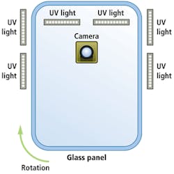
In the VRSI application, the size of the automotive glass panel requires that at least six lines of UV LEDs be used. Six L300 Linear Lights from Smart Vision Lights were placed so as to illuminate one half of the panel edge. The camera was located so as to be directly below the center of each half as the panel after it was positioned for inspection (see Fig. 1).
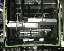
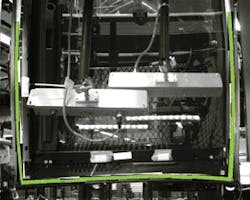
Captured images clearly show the absence of primer on half the glass edge or multiple skips and breaks in the application of primer (see Fig. 2). In cases in which primer application is inadequate, the operator is alerted that the primer has not been applied effectively and the panel must go back for reapplication.
Once the inspection is remade, if the glass panel is acceptable, then the robot rotates the part to inspect the other half of the glass (see photo on p. 59). When this half passes inspection, the glass panel is ready to be urethaned and decked for final installation.
At this point we do not know what the return on investment is for this automotive company. But it can be certain that this step in its assembly process will be nearly 100% efficient.
Acknowledgment
We would like to thank Variation Reduction Solutions and McNaughton-McKay Electric Company—Vision & Traceability Group for their support in writing this article.
Matt Pinter is engineering manager at Smart Vision Lights, Muskegon, MI, USA; www.smartvisionlights.com.
UV 395 or 365
When using UV light in a machine-vision application, there are a few critical issues to consider. Ultraviolet wavelengths of 395 and 365 nm are viewed very similarly by CCD or CMOS cameras. One should never assume that 365 nm is the only UV wavelength that will excite the object under inspection. This type of assumption can lead to trouble and multiply the cost of lighting.
The vast majority of applications will work with 395 nm lighting (see figure). In most cases 395 nm will do a better job at exciting the object. This is due to the higher wattage for 395-nm LEDs, which produces more energy. The other drawback to using 365-nm lighting is that LEDs for this wavelength are significantly more expensive than 395-nm LEDs. They can be from 5 to 10 times more costly.
The most impressive solution requires pairing 395-nm lighting with the correct lens filter to provide a crisp image and a cost savings. Even with a color camera and applying filters, there is not much improvement in the images. Although all applications need to be tested, experience has shown that 95% of applications can use 395 nm wavelengths. For most machine-vision applications requiring the use of UV lighting, the most important aspect is finding the best filtering, while the wavelength of the light source does not play as large of a role.
null
