Retrieval at Sea
A unique vision-guided robotic system will retrieve unmanned US Navy boats
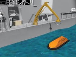
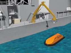
The US Navy uses powered, unmanned boats for various operations. Retrieving the boats from the water quickly and safely is a challenge. To meet this need, the US Small Business Innovation Research (SBIR) program awarded a grant to promote the development of a retrieval system to Allied Systems Company, a manufacturer of heavy-duty marine crane robotics.
To move from concept to development of a scale working model, Allied Systems joined with Concept Systems—a custom integration company. Concept Systems, in turn, drew upon its automation project experience, contacting leaders in the areas of vision and motion control. The result is AutoLARs (automatic launch and recovery system).
Doug Taylor, Concept Systems lead engineer, says that the project began as a brain-trust between himself and his counterpart from Allied Systems, Joel Dille. “We actually started with a LEGO model that Joel put together at home. We watched videos on retrievable systems and went to conferences,” he says.
After a period of testing different theories and mechanics, the foundation of AutoLARs started to come together. “It’s essentially an autonomous crane that uses feedback from vision software to hoist small unmanned surface and underwater vessels back onboard when their mission is complete,” Taylor says. “This is not an easy task, as the ocean is not a static entity.”
System in motion
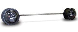
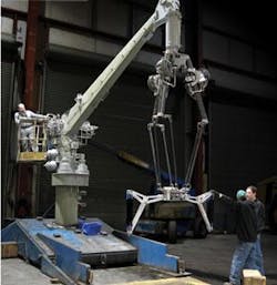
The mechanics consist of a three-legged end-effector mounted to an articulated crane. This unique end-effector utilizes three separate and adjoined articulating arms, with a single strut for the upper arm and a double set of struts for the lower arm. Both the upper and lower arms are approximately 45 inches long. The end of the effector has a spreader arrangement along with an interference fit style of coupler. This basically garrotes and cradles the target for retrieval (see Fig. 1).
After the basic mechanical design was set, the next step was to give it operating senses. A dual-camera system provides the vision and a Delta Tau drive was chosen to handle the motion of the crane and end-effector. A Cognex vision platform integrated the cameras with the rest of the system.
Concept selected a pan/tilt unit that could swiftly and accurately move the cameras throughout a wide range. To allow retrieval of information in real time, the unit was retrofitted with encoders. An enclosure was designed, based primarily on the spherical lens provided by Edmund Optics. This allowed each camera approximately 180º (side to side) and as much vertical movement as possible. A Schmitt Industries/Acuity AR4000 laser rangefinder was added for initial calibration of the vision system.
Concept finalized the design with the addition of affine transform and vector calculations to make the system very flexible in setup and calibration. Using a calibration target permanently mounted to the end-effector (a black-on-white doughnut shaped from adhesive vinyl, 5.5-in. OD and 3.5-in. ID spot), the end-effector only needed to move through four separate points to perform a complete calibration of the entire system.
Simultaneously, the developers contacted Mark Siddall, a research physicist, to help develop prediction algorithms. The system could see, think, and move to a proper target, but it also had to be able to anticipate where that target might be in an ocean that is in continual motion.
Vision control system
The control system for this project was constrained by the requirement to use typical off-the-shelf components unless absolutely necessary. With this in mind, the project was divided into two major subsystems—the vision-control system and the motion-control system.
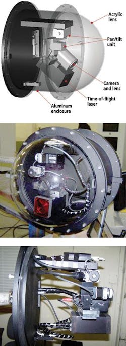
The vision system starts with two Sony XC-HR70 cameras in identical enclosures. The construction of the outer shell is powder-coated aluminum finished in a flat black. The front has an optically clear acrylic half-sphere lens. The entire enclosure is sealed using rubber gaskets and sealed bulkhead pass-through devices that render the system waterproof (see Fig. 2).
The vision system is built around the Cognex VisionPro libraries in a Microsoft Visual Basic 6.0 environment running in a Microsoft Windows XP professional operating system. “We had worked with Cognex before and felt that its ability to find a vision solution for a difficult environment was unsurpassed,” Taylor says.
The major components of the vision system include a Dell XPS desktop Pentium Extreme Edition system with dual-core Pentium processor; two 19-in. LCD monitors; and a Cognex MVS-8504 four-channel frame grabber. Taylor says, “The two Sony HR-70 cameras with Pentax H6ZBME zoom lenses are located about eight feet apart. While the system is binocular, it can be quadocular as well. So we knew we needed at least two cameras and the Cognex 8504 board allows up to four.”
In addition each enclosure contains a Directed Perception PTU-46-70W weatherized pan/tilt control system and a US Digital PCI-4ED four-channel quadrature encoder card with two Encoder Products hollow bore encoders mounted directly to the pan/tilt control system.
Each enclosure also includes a Schmitt/Acuity Measurement Systems AR4000 time-of-flight laser rangefinder capable of one-tenth inch accuracy throughout the 50-ft range; a custom mounting plate designed to adapt the camera and laser to the pan/tilt unit; and a custom harsh-environment enclosure built using an Edmund Optics P85-216 plexiglas dome, making the enclosures suitable for sea operations during the final phase of the project. The Opto 22 SNAP Ethernet-based I/O subsystem consists of the B3000 Ethernet-based controller, eight channels of relay output , four channels of AC input, and four channels of AC output.
The cameras provide a 1024 × 768-pixel image, with each pixel providing an intensity value from 0 to 255 (8-bit black-and-white image). The physical shape of the pixels is square, so they are easily used to measure objects regardless of orientation of the object to the camera. These data are communicated at a maximum rate of 30 frames/s, depending on exposure time, over a high-speed analog interface to the frame grabber. The motorized zoom lens has been adapted to provide remote zooming and focusing while the iris is completely opened (see Fig. 3).
The key to operation is simultaneous image acquisition. “We need to see where the target is in real time, and the Cognex frame grabber allowed us to do that,” Taylor says. “The reason we chose the Sony HR70 cameras was the balance between picture rate and data—1024 × 768 seemed like a good balance. The Pentax lens can automatically zoom out when it gets within range and allows the system to coordinate in time.”
One unusual aspect is that this vision system uses only ambient daylight. “It uses a series of UV lamps in dead night,” Taylor says. “During the day it emits no energy. We didn’t have to do that, but we felt people’s lives might be at stake. Since this is a shallow-water operation, it is within eyesight of the shore. If we did use any lights we wanted to use only those that wouldn’t be seen from a beach at night.”
While the laser system is a key to calibrating the vision target, it is turned off 99.9% of the time. “The cameras give two angles, but not the radius or spherical coordinates,” Taylor explains. “The laser does that during calibration. Once that is done, it rarely needs to be done again. We chose the Schmitt Measurement System. because it’s the best laser on the market and accurate to one-tenth inch at 50 feet.”
Motion control system
Concept and Allied had to develop a kinematical model to make the full system move smoothly. AutoLARS is designed to locate the target and to automatically make decisions on how the motion axis should react based upon which mode the system is in. This creates a large information infrastructure (see Fig. 4).
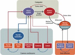
The motion system consists of a Delta Tau universal motion axis controller (UMAC) system. A single program resides in the system PC along with a series of interconnected programs running in the Delta Tau control system. The motion program receives target x-y-z data from the vision system in effector coordinates. The program feeds the effector position to the vision system over the TCP/IP connection,
“The Delta Tau UMAC is an extremely fast motion-control system capable of closing potentially all 32 axes involved with as many as 16 coordinated axis systems in 0.44 ms,” Taylor says. “The main reason we selected this control system was its kinematical modeling capability. In short, it is possible to teach the motion-control system the dimensions of the end-effector along with the mounting angles and pivot points so you can command the end plate in x-y-z coordinates, as well as give it a move speed, and not have to calculate the individual cylinder positions, or their targeted speed profiles. The usefulness of this feature cannot be overstated” (see Fig. 5).
Prediction
Prediction is a required function for this system. It basically needs to tell the controller, “I know where my target is and I know where it has been, but for me to pick it up quickly, I have to predict where it’s going to be in the next few seconds.”
“It’s a very fast moving system,” Taylor says. “But there are limitations. When taking it to full size, the motion system will be speed-limited at some point, and prediction has to take over. The larger scale the system gets, the harder it is to perform at the same level as the smaller-scale system.”
AutoLARS grabs one picture every 60 ms and feeds it back into the prediction algorithm. “The way we determine if we have a good prediction is to predict forward and extend that to the past. How accurately it predicted the past is how accurately it will predict the future,” Taylor explains. “Right now, we have been testing this by setting it to automatically pick up moving targets. There’s nobody controlling the robot. The prediction is doing that.”
Next phase
Today, the system is fully functional and waiting for approval to take it to full size and test it in action (see Fig. 6). “The actual working system will be well over 30 feet high,” Taylor says. “This second phase was to develop a scale model, where the robotic end is approximately one-third the final size, but all the components controlling it—vision, motion, and control—are the final working systems.”
AutoLARs needed a vision system that was good enough to allow the system to accurately predict and send data to the control system. In turn, the control system had to feed all the information to the mechanics to create something that could actually be used. “The ocean is really random. We still have work to do. We are thinking of adding underwater pressure sensors that will be leading indicators. Prediction is what makes this different from other retrieval systems,” Taylor says. “Building the final full-size model and tuning all the input for use in real-world conditions is the next stage.”
null