Vision system monitors ink jets
Currently, the two most popular types of ink-jet printers use either thermal bubble or piezoelectric print heads. In a thermal ink-jet printer, such as produced by Canon and Hewlett-Packard, the ink-jet head is made up of a linear array of resistors. When current is applied to these resistors, the resulting heat vaporizes the ink, creating a bubble that is expelled from the ink-jet nozzle onto the paper. In piezoelectric-based print heads, the charge is applied to a piezoelectric crystal pint head array that vibrates, expelling ink though the print-head nozzle.
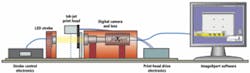
“To test the performance of these ink-jet designs,” says Yair Kipman, president of ImageXpert (Nashua, NH, USA; www.imagexpert.com), “it is necessary to monitor the drop volume, velocity, and trajectory of each drop as it emerges from the print head at approximately 10 m/s.” To analyze drops-in-flight, Kipman and his colleagues have developed a system that uses off-the-shelf machine vision components coupled with a custom-built triggering and LED light strobe interface (see Fig. 1).
To illuminate the ink droplets as they are ejected form the thermal printer, the jetXpert system uses a single LED illuminator from Philips Lumileds (San Jose, CA, USA; www.lumileds.com) coupled to a collimating lens. “Because the droplets need to be backlit as they emerge from the print head,” says Kipman, “collimating the light source ensures that more rays will enter the camera’s lens and then the camera.”
Coupling this collimated light with a Moritex zoom lens Ink-jet continued from page 11 (Cambridge, UK; www.moritex.com) ensures that should an ink drop move even slightly within the depth of field, there will no associated magnification change. A 1024 × 768 (active array) Stingray camera from Allied Vision Technologies (Stadtroda, Germany; www.alliedvisiontec.com) captures images that are transferred over the camera’s FireWire interface to the host computer.
Although the Stingray camera runs at 30 frames/s, the camera also features a variable shutter speed that can be adjusted from 48 ms to 67 s. “Triggering the camera for 48 ms within each frame,” says Kipman, “allows for better image quality, since fewer droplets are being aggregated in the image.”

Because of this, the ink drop itself is clearly visible, and the volume, velocity, and trajectory can then be measured (see Fig. 2). One of the major tasks was the development of a custom strobe-controller board. “To ensure that an image is properly captured,” says Kipman, “it is necessary to properly synchronize the firing of the ink-jet print head with the LED strobe light.”
Using a microcontroller from Microchip (Chandler, AZ, USA; www.microchip.com), timing from the manufacturer’s print-head controller is passed though delay logic, allowing the output stage of the controller to drive the LED strobe. “Building a digital controller that has this level of control over the strobe,” says Kipman, “allows the system to be configured to measure output from a number of different print heads from a variety of manufacturers.” This permits JetXpert to be used to analyze output from any print head, including those from Kodak, Toshiba Tec, Konica Minolta, Xaar, and Spectra.
Interfaced to the host computer via an RS-232 serial port, the microcontroller board controls the LED strobe based on settings entered into a custom GUI. Settings include strobe pulsewidth (down to 500 ns), strobe delays, and single, double, or triple dot visualization. “Providing a short 500-ns pulsewidth,” says Kipman, “ensures that an ink-jet drop traveling at 10 m/s will travel a maximum distance of 0.005 mm during the strobe exposure time, minimizing motion blur.”
ImageXpert software is used for image analysis. As images are captured, they are transferred to the host computer for processing. Analysis includes drop volume, velocity, and trajectory.
To measure the speed of the drop, the distance between the center of gravity of two blobs is computed. Because the timing between these two blobs is accurately known by the digitally set strobe delay time, the velocity can be calculated easily.
One of the most important measurements required by print-head designers is the trajectory of each ink droplet. Ideally, this should be at 90º to the print head but may vary with different ink-jet designs. To calculate trajectory, the angle between the ejected droplets and the ink-jet print-head nozzle plate is measured.
To more accurately determine a drop’s trajectory, ImageXpert offers a two-camera version of the system that will mount two Stingray cameras at 90º to each other. “Thus,” says Kipman, “the trajectory of each drop will be able to be more accurately determined.”
Analysis of drops-in-flight is important not only to manufacturers of print heads and inks, but also to those jetting and dispensing other materials such as functional fluids (conductive ink for printed electronics, for example), adhesives, and bio materials. Costing approximately $28,000, the jetXpert system is under evaluation by some large ink-jet print-head manufacturers. In addition to offering a single-camera system, Kipman offers a two-camera system and another option that incorporates a stepper-motor controller from Newport (Irvine, CA, USA; www.newport.com). Although these systems are somewhat more expensive, they offer more capabilities—from full trajectory analysis for the two-camera system to automating inspection of ink-jet print head for the motion system.