Image Processing: Open-source system wins VISION Award

Every year at the annual VISION 2008 tradeshow in Stuttgart, a particular company is singled out to receive the VISION Award, donated by Messe Stuttgart to honor innovation in the machine-vision industry. Although past winners of the award have included such companies as Silicon Software (Mannheim, Germany; www.silicon-software.com) for its VisualApplets graphical software for FPGA processing and CMOSVision (Schaffhausen, Switzerland; www.cmosvision.com) for its Image Correction Processor, this year’s winner was different.
Rather than bestowing the award on a particularly novel hardware or software development, the prize was awarded to Supercomputing Systems (Zurich, Switzerland; www.scs-vision.ch) for its leanXcam intelligent color camera. Indeed, in his acceptance speech when receiving the award, Reto Bättig, department head of Supercomputing Systems, admitted that the technology behind the camera was not particularly innovative. Instead, the business model that the company plans to pursue to market and develop further smart camera products makes his company unique.
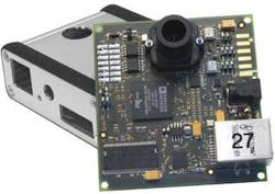
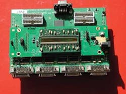
This business model is based on the concept of open-source computing for intelligent cameras. In the design of the smart camera, Bättig chose to interface a 1/3-in, 752 × 480 resolution, 60-frame/s CMOS sensor from Aptina Imaging (San Jose, CA; www.aptina.com) to a ADSP-BF537 Blackfin processor from Analog Devices (Norwood, MA; www.analog.com). The single-board smart color camera sports an Ethernet, RS-232, and digital I/O interfaces, 64-Mbyte SDRAM, and 8 Mbytes of on-board flash memory.
As can be seen, the design is hardly revolutionary. What is revolutionary is that Supercomputing Systems has published the schematics, layout, and components at www.leanxcam.origo.ethz.ch/ and made these freely available under an open-source hardware license. Here, camera designers can also download data sheets and print layouts of the leanXcam hardware.
For developers wishing to evaluate the camera and the free software, the company also offers a demonstration version of the camera for €260. Perhaps more important, the leanXcam runs under the open-source operating system μClinux (www.blackfin.uclinux.org/gf/), a Linux distribution built from the Linux kernel (available at kernel.org) and software from the GNU project (www.gnu.org) from the Free Software Foundation (www.fsf.org) This provides the software developer with a number of free open-source applications that include image capture, manipulation, and web services.
To abstract the hardware of the leanXcam and allow simple functions to be implemented by developers, Supercomputing Systems also offers the OSCar (Open-Source Camera) Software Framework. This library of programs is also freely available together with the source code available as a GNU Lesser General Public License (LGPL), also from the Free Software Foundation. Templates for new projects and demo programs are also available, which include a graphical user interface (GUI) from which live images can be sent to a PC, displayed, and stored.
According to Men Muheim, project engineer with Supercomputing Systems, students from the Swiss Federal Institute of Technology (ETH; Zurich, Switzerland; www.ethz.ch) and the University of Applied Sciences (ZHAW; Winterthur, Switzerland, www.zhaw.ch/en.html) are already using leanXcam and will place any software developed back in the public domain. Better still, the leanXcan is already finding uses in industrial applications.
For Ferag AG (Hinwil/Zürich, Switzerland; www.ferag.ch), a manufacturer of conveying, binding, inserting, and stitching machines for the newspaper and magazine post-processing industry, for example, an industrial version of the camera was developed to monitor the correct folding of magazine forms before they are finally bound.
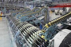
“As folded forms progress along the machine, it is imperative that they are properly situated so that they can be perfectly bound by a binding machine,” says Muheim. “Should any form be incorrectly positioned, then it must be rejected from the machine.” As up to 12 lines of forms pass through the folding machine at rates of approximately 10 per second, 12 leanXcam cameras linked via Ethernet capture images of each form. These images are then compared with a golden template.
“Should any form be incorrectly positioned, the Blackfin DSP then triggers a digital output that is used to reject the form from the machine,” says Muheim. To train the system, Supercomputing Systems used a proprietary pattern-matching algorithm embedded in the camera’s DSP. In operation, the operator starts the system and more than 100 captured images per camera are used to teach a golden template that contains various features of the form. In this way, the embedded vision system can rapidly adapt to new forms that may be presented and the folding machine restarted for the next batch of forms.
Certainly the business model set forth by Supercomputing Systems is interesting. However, other camera vendors in attendance at the award ceremony in Stuttgart were more skeptical, questioning how the company could possibly survive based on such a model and the still untested commercial support of open-source systems. With the lack of support for most of Microsoft’s latest operating systems, however, it seems that open-source embedded camera systems are here to stay.
Machine-vision Systems: New technologies and products go on show at VISION 2008
What has become the world’s largest machine-vision and image-processing tradeshow, VISION, is held every year in Germany. This year’s show, held from November 4–6 in Stuttgart was even larger than the previous year, boasting more than 300 exhibitors and a record attendance of more than 6,000 visitors. What made the previous year’s show particularly memorable was that established companies shared the exhibit space with lesser known start-ups and research centers, all of which presented some novel and interesting technologies and products. To add to this, many established and lesser known companies chose the show to introduce these new technologies and products, providing an extra incentive for visitors to attend.
As with any high-technology event, the smaller/faster/cheaper/digital mantra held true at VISION 2008 with companies introducing high-speed, high-resolution sensors, smart cameras, and software. As expected, the interest in CMOS imagers remained strong this year with at least three companies announcing new devices, camera development systems, and cameras based around them.
While Awaiba (Madeira, Portugal; www.awaiba.com) introduced its first commercially available CMOS linescan imager series, others such as Smart Systems (Vienna, Austria; www.smart-systems.at) introduced a smart CMOS linescan imager and a camera system that is currently being used in a high-speed counting application. For its part, Cypress Semiconductor (San Jose, CA, USA; www.cypress.com) extended its LUPA family with the LUPA-1300 1280 × 1024 color imager with a pipelined synchronous shutter and on-chip LVDS outputs. The company also showed its 3-Mpixel, 485-frame/s imager, which boasts an impressive 13.2-Gbit/s throughput that is currently being used in holographic data storage applications.
If any one product category could have been said to have stolen the spotlight at VISION 2008, however, it would have been cameras. At the show, numerous camera vendors showed products with a disparate range of features and interfaces targeted to a range of different markets. This year, however, it was not just the products themselves that were interesting, it was the business model that some of the camera vendors at the show had adopted to sell their cameras.
Indeed, the winner of this year’s VISION prize, Supercomputing Systems (Zurich, Switzerland; www.scs-vision.ch), announced a DSP-based camera that the company has made freely available under an open-source hardware license. Kamiera (Hod Hasaron, Israel; www.kamiera.com) was also making a pitch for what it calls OpenCam, a concept that allows companies to manufacture their own cameras rather than purchasing them off-the-shelf.
Customization was also the theme at both Softhard Technology (Marianka, Slovak Republic; www.softhard.com) and Imaging Solutions Group (ISG; Rochester, NY, USA; www.isgchips.com) where both companies were showing a number of different camera modules and integrated camera systems. Where time-to-market is key, however, purchasing an off-the-shelf camera system rather than developing your own may be a more prudent idea, especially when the cameras may be relatively expensive or require a high level of software support.
Perhaps no single-volume application, for example, would warrant building a high-resolution 50-Mpixel camera from scratch, given that a camera with these specs—the XMV-50100, a full-frame, 50-Mpixel camera—is already available from illunis (Minnetonka, MN, USA; www.illunis.com). Using the latest KAF-50100 imager from Kodak (Rochester, NY, USA; www.kodak.com), the camera boasts an 8176 × 6132 × 14-bit resolution and minimum 0.5-ms exposure time, and is offered with either a Camera Link or GigE Vision interface.
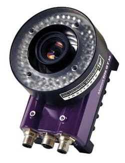
Similarly, in rugged industrial applications where a camera system may need to be reconfigured to perform many different tasks, the latest smart camera from Matrox Imaging (Dorval, QC, Canada; www.matrox.com/imaging) may be a better option. Dubbed the Iris GT, the camera features an Intel 1.6-GHz Atom processor and Windows CE 6.0. With an integrated graphics controller with VGA output and 256-Mbyte DDR2 memory, the camera includes a 10/100/1000 Ethernet port, USB 2.0 port, RS-232 serial port, optocoupled trigger input, and strobe output.
Initially available in two monochrome sensor configurations, a 640 × 480 version running at 110 frames/s and a 1280 × 960 version running at 22 frames/s, the CCD-based camera is available either with the Matrox Design Assistant interactive development environment or with the Matrox Imaging Library (MIL).
Reducing the integration time of industrial cameras was the theme on the booth at LMI Technologies (Delta, BC, Canada; www.lmitechnologies.com). There, the company demonstrated its latest maestro lighting and I/O controller interface designed to reduce the integration time of developers building machine-vision systems. The P800 module interfaces encoders and I/O with a single power supply that can be used to synchronize up to eight GigE Vision and FireWire cameras. As a companion product, the C12 module is a camera and lighting controller that is connected to the P800 with a 100-m Cat5 cable. This module is used to power and trigger the cameras and provide a current source for LED or laser illumination.
The larger, more established companies such as Matrox and Stemmer Imaging (Puchheim, Germany; www.stemmer.de) showed the latest upgrades to their software, most notably in the area of parallel image processing. Eager to compete, less well-known vendors such as Future Processing (Bytom, Poland; www.adaptive-vision.com) and Neurotechnology (Vilnius; Lithuania; www.neurotechnology.com) also showed new software packages targeted toward machine vision.
Future Processing chose the show to announce its Adaptive Vision Studio, a PC-based machine-vision software package that can be used to perform shape inspection, blob analysis, measurement, and barcode measurement. For its part, Neurotechnology debuted SentiSight, a €360 PC-based package in which objects within an image are learned and later recognized at rates as fast as 20 frames/s (using 320 × 240 images).
Perhaps the only missing piece to last year’s event was the migration of biologically inspired software and systems. No institutions or companies showed cameras based on insect or human-like vision, choosing instead to offer products based on established CMOS or CCD devices. And although buried in certain software packages, as yet no software package offers high levels of image understanding based on the human visual system. Despite the huge success of VISION 2008, the machine-vision industry seems far from mature.
INDUSTRY STANDARDS: Pre-emphasis increases Camera Link cable distances
One of the most important limitations of the Camera Link standard is the maximum distance that can be achieved between the cable connecting high-speed cameras and frame grabbers. At present, this distance is specified by the AIA Camera Link committee as between 8 and 10 m for an 85-MHz Full Camera Link signal as generated, for example, by the A406k 8-bit, 10-tap from Basler (Ahrensburg, Germany, www.baslerweb.com).
“Even though this distance is specified as achievable by the committee,” says Ray Berst, president of Components Express Inc (CEI; Woodridge, IL, USA; www.componentsexpress.com), “in reality, many cables currently available cannot achieve this distance without some loss of image data.” For developers of cameras, cables, and frame grabbers, this situation is worrying, since when systems do not perform as required the systems integrator may lay the blame on camera and frame grabber vendors whose products perform as advertised. Perhaps even more worrying, the Camera Link cable subcommittee currently only specifies that the image integrity of transmitted data need be specified one tap at a time.
“While transmitting 8 bits of image data over one Camera Link cable of 10 m in length may be perfectly achievable and result in no transmission errors,” says Berst, “when multiple taps are used, the bit-error transmission rate (BERT), or the ratio of number of errors to total number of bits transmitted, increases dramatically.”
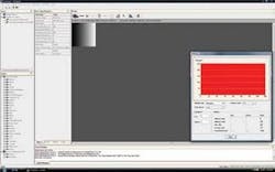
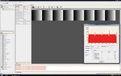
At VISION 2008 in Stuttgart, CEI demonstrated the effects of this image degradation using a leading brand Camera Link cable. Using a test gradient or wedge image that smoothly translates from black to white over an 8-bit grayscale and plotting the histogram of the received image, it is apparent there is an equal spread of differing pixel values across the image when a single tap data is transmitted. However, when eight-tap data is transmitted noise is introduced into the image that can clearly be seen by the erroneous data in the histogram.
“Camera Link cable manufacturers that use single-tap transmission data can therefore present erroneous data to their customers by just using a single-tap test, and this is the current means of cable testing proposed by the Camera Link cable subcommittee,” says Berst. “Not only does this test present erroneous data, it also requires cable vendors to spend hours verifying the integrity of their cables.” Perhaps a better way of specifying the performance of these cables, and one proposed by CEI, is the BERT test that would allow a more complete cable specification to be offered to system developers and allow cable vendors to certify performance of every cable.
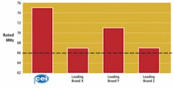
To accomplish this, input data as high as 112 MHz would be transmitted along the cable using all eight taps at 8 bits/tap. After 1000 images were transmitted, the transmitted and resultant images would be compared and analyzed. Of course, at 112 MHz, many cables would fail the BERT test. However, Berst proposes this rate would be incrementally lowered until a specific cable length and frequency could be achieved with no bit errors.
To illustrate this concept, CEI tested a number of leading brand cables in this manner. As can be seen, while many cable vendors specified their 7-m Camera Link cables capable of running at the full 85-MHz camera rate, in actuality, these rates ranged from 75–85 MHz.
“To increase the cable distance of Camera Link even further than 10 m,” says Berst, “a process known as transmit pre-emphasis can be used to boost the transmit signal, which counteracts the effects of attenuation.” Interestingly, this pre-emphasis is one of the features already embedded in the Channel Link SerDes chipset offered by National Semiconductor (Santa Clara, CA, USA; www.national.com).
However, this feature is often not enabled by camera vendors. If it were to be enabled, a manual potentiometer used in conjunction with the LVDS chipset used in the Camera Link standard could be used to increase the transmission distance between cameras and frame grabbers. “Of course,” says Berst, “this would require manual tuning between both the camera and the frame grabber and would be a time-consuming and repetitive process.”
Rather than take this approach, CEI has developed a new line of patent-pending Camera Link cables that integrates pre-emphasis into the Camera Link cable. This allows CEI to offer Base Camera Link cables running at 85 MHz to extend as far as 25 m and Full Camera Link cables also running at 85 MHz to extend as far as 17 m with no signal degradation.
To accomplish this, the Camera Link cable incorporates a set of Channel Link processors that convert the Camera Link signal from the camera to an LVDS signal. A second set of Channel Link processors then adds a specific pre-emphasis to the signal before it is transmitted along the Camera Link cable.
“In this way,” says Berst, “both camera and frame grabber vendors need not concern themselves with pre-emphasis since this is now built into the cable itself.” At VISION 2008, CEI demonstrated the first prototypes of the cable using a Basler A406k camera transmitting 85-MHz Camera Link data over a distance of 17 m.
IMAGE capture: CMOS sensors target multiple applications
After working at the CMOS image sensor group of IMEC (Leuven, Belgium; www.imec.be), Martin Wäny developed and patented his work as a PhD student at CSEM (Neuchâtel, Switzerland; www.csem.ch), developing the world’s first combined linear logarithmic sensor. Based on this patent he spun off Photonfocus (Lachen, Switzerland; www.photonfocus.com) to market the technology.
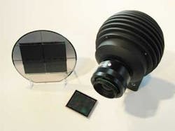
After leaving Photonfocus in 2004, Wäny founded Awaiba (Maderia, Portugal; www.awaiba.com) to pursue the development of custom CMOS imagers. Although much of the company’s work remains proprietary, it did announce a range of linescan CMOS imagers, including the world’s largest commercially available 16k × 1 imager at VISION 2008 in Stuttgart.
From a semiconductor engineering perspective, the device decouples the integration capacitance from the photodiode area, resulting in a high conversion gain and linearity. By using a buried MOS channel, the effects of noise generated by surface states in the MOS channel of the front-end amplifier next to the photodiode are reduced.
After charge integration, per-pixel processing consisting of correlated double sampling (CDS)—to further reduce noise—sample and hold (S/H), and analog-to-digital conversion is used before the final result is shifted to a 13-bit readout register. “Using an on-chip 13-bit ADC,” says Wäny, “provides the camera designer with a useful 12 bits/pixel of image data.”
To his credit, Wäny has benchmarked the noise figures of the device along with other 40-MHz, 7 × 7-μm linescan cameras from the three large linescan camera manufacturers. From the company’s figures, its CMOS linescan imager performs better than these companies’ CCD-based cameras in terms of low noise and SNR at a given number of impinging photons/pixel.
Running at 40 kHz, the device uses sixteen 12-bit-wide digital taps organized in an odd/even order. This results in a readout frequency of 50 MHz per tap or 1.6 Gbytes/s. To demonstrate the design of a camera based on the 16k × 1 imager, Awaiba has put together a €20,000 camera demonstration setup that includes the sensor, the company’s sensor evaluation board (which sells for €2200), a 60 × 60-mm format lens from Schneider Kreuznach (Bad Kreuznach, Germany; www.schneiderkreuznach.com), and is based on two Camera Link Full data interfaces running in parallel. Because the data rate of the camera is 1.6 Gbytes/s and the maximum data rate of the Camera Link interface is 680 Mbyte/s, two Full Camera Link interfaces are required to transfer image data in real time from the evaluation board to the PC.
“As 12-bit image data is streamed from the 16 taps at 40 MHz,” says Wäny, “it is formatted by two Xilinx FPGAs and transferred to two independent sets of Full 80-MHz Camera Link transceivers.” These two Full Camera Link interfaces then transmit image data to two Full Camera Link microEnable IV-Full Camera Link frame grabbers from Silicon Software (Mannheim, Germany; www.silicon-software.com), where they are stored and processed in the PC.
Awaiba also offers a number of other sensors based on the same technology with differing numbers of pixel elements and pixel sizes as the Dragster product line. These include 2k × 1, 4k × 1, and 8k × 1 devices with 7 × 7-μm pixels; 4k × 1, 8k × 1, and 16k × 1 imagers with 3.5-μm pixel sizes; and 2k × 1, 4k × 1, and 8k × 1 image sensors with 7 × 500-μm pixel sizes.
While the 4k × 1 sensor with 7 × 7-μm imager has already been integrated into a linescan camera by Neopt Corporation (Kawasaki, Japan; www.neopt.co.jp), Wäny expects devices with 7 × 500-μm pixels to be used in more specialized applications such as spectroscopy and structured light imaging, where the larger pixels will allow cameras and spectrophotometers with higher sensitivity to be developed.
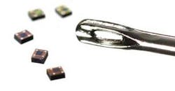
As well as introducing the world’s largest commercially available linescan sensor, Awaiba chose VISION 2008 to introduce possibly the world’s smallest area-can CMOS camera. With 140 × 140 pixels, the imager used in the camera measures 540 × 500 μm and can produce 8-bit/pixel images at up to 40 frames/s.
To produce the camera, it was necessary to fuse the lens directly onto the imager, a process that was accomplished by a subcontractor to Awaiba. After on-chip digitization, digital data is then transmitted over a USB interface for display. Dubbed the NanEye, the camera is expected to find uses in medical applications such as digital subtraction angiography where a surgeon may need to visualize the interior workings of the heart before performing surgery.