Dynamic Design

Andrew Wilson, Editor
In machine-vision applications such as robotics and security, the ability of a sensor to image a scene that may range from very light to very dark is important. In vision-guided robotic systems, for example, an imager may be required to monitor weld beads as they are being welded and to check the integrity of the weld after it is formed. To do so requires capturing images in the presence of a bright welding light and then an image of the weld after it is welded. Similarly, cameras used in security systems must operate both in daylight and nighttime conditions to produce images that can be interpreted either automatically or manually.
While the human eye and photographic film may be capable of resolving images with a high dynamic range, most currently available CCD and CMOS image sensors cannot achieve this goal. In the past 10 years, however, sensor architects have developed a number of ways to increase the dynamic range of their devices.
The dynamic range of an image sensor is the ratio of the largest nonsaturating input signal to the smallest detectable input signal. Consequently, increasing the dynamic range of CMOS and CCD imagers is achieved either by increasing the largest nonsaturating input signal or decreasing the smallest detectable input signal. In most high-dynamic-range imagers, the former method is used.
Many different sensor architectures using both CCD and CMOS technology have been used to increase this dynamic range. While many of these architectures or variations of them have been applied in commercial sensors and cameras, some remain the subject of ongoing research. Architectures include those that feature dynamic well capacity adjustment, multiple image capture, spatially varying exposure times, time-to-saturation architectures, logarithmic transfer functions, and local intensity adaptation.
Dynamic wells
In well capacity adjustment, dynamic range is increased by resetting the integration time of the sensor one or more times during integration. In active pixel sensors, such as the IBIS-5 image sensor from Cypress Semiconductor, bright pixels with a higher well capacity are reset and those darker pixels with a low well capacity receive a longer integration time. This controls the saturation of the imager and increases the dynamic range (see Fig. 1).
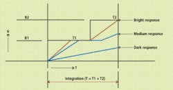
Melexis also uses this technique in the design of its MLX75411 (Avocet) CMOS APS imager. Using the company’s Autobrite technology, the response curve and the total integration time can be dynamically adjusted based on the imaged scene. This dynamic range is expanded in real time by changing the timing and height of the reset signal (see Fig. 2).
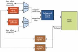
After the image sensor captures an image, registers acquire the average intensity and number of pixels that exceed a threshold. The statistics are then used to select the optimum response curve and integration time. A multiplexing device inputs the signals and allows either the calculated values or user-supplied values to be fed to the voltage and timing control, which generates reset voltage for the image sensor.
Simultaneously calculating both the integration time and the required dynamic range expansion allows the image sensor to settle quickly on optimal settings. This is critical in automotive applications where dramatic changes in lighting conditions occur rapidly.
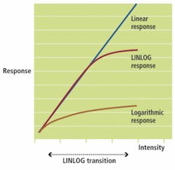
Using the well capacity adjustment technique, Photonfocus has developed a method known as LINLOG that combines both a linear and logarithmic response in each pixel, preventing the slow response time and reduced contrast shown in traditional logarithmic image sensor designs (see Fig. 3). By using a linear response at low illumination levels and pseudo-logarithmic compression at high intensity levels, LINLOG devices have been shown to exhibit a dynamic range of 120 dB. The architecture of the Photonfocus CMOS sensor also permits the operation of the pixel array in pure logarithmic mode, which results in a wide dynamic range.
Resetting the integration time of the sensor is not the only method used in today’s high-dynamic range imagers. Other methods such as full logarithmic compression can also be used. Such designs achieve high dynamic range by using logarithmic compression as each photodiode’s photocurrent is converted to voltage. This is the approach used by IMS Chips in its high-dynamic-range CMOS (HDRC) range of imagers that are incorporated in CMOS cameras from Gevitec.
In traditional logarithmic approaches when photocurrent values are very small, integration time may become excessively long, resulting in an image lag when the camera is moved from bright to dark scenes. To overcome this limitation in its range of imagers, IMS uses an active feedback approach to reduce image lag. A 640 × 480-pixel image sensor has been incorporated into the Gevilux CCTV camera, a 30 frames/s camera that exhibits a dynamic range of 120 dB.
Multiple exposures
An equally effective way to increase dynamic range is to capture multiple exposures of an image at different light levels. In this method, shorter integration times can be used to capture bright images and longer integration times for darker images. This approach is beneficial because the signal-to-noise ratio (SNR) is maintained over the extended dynamic range and the image sensor still exhibits a linear response. Although multiple image capture times are possible, most often dual-capture designs are realized.
Fundamentally, this is the concept used by Panasonic in the Super Dynamic technology in its range of security cameras. Introduced in July 2000, Panasonic’s cameras based on this technology incorporate a double-speed CCD and a DSP, imaging a scene at 1/60 s and 1/8,000 s. Just as the long exposure captures darker portions of the image, the short exposure captures the brighter portions. The two exposures are then combined to form an image with a dynamic range that the company claims is 64 times greater than that of standard CCD-based cameras.
Spatially varying
Perhaps one of the most obvious methods to increase the dynamic range of image sensors is to use a spatially varying exposure. Rather than capture these images using temporal approaches, a filter array is deposited on the sensor so that in a single image capture high-brightness regions are captured by those pixels with higher-density filters and low-light levels are captured by pixels with low-density filters.
Although this method is simple to implement, filtering incoming light reduces the sensor’s sensitivity and SNR. Also, because the spatial resolution of the sensor is reduced, a higher spatial resolution is required to achieve the same resolution using other techniques.
Using this technique, Awaiba has developed a patented technology that permits the assignment of different exposure times to different pixels in the same frame capture. The technology allows pixels to be assigned four different integration times on a frame-by-frame basis.
This approach assigns long integration times to dark areas of the image and short integration times to pixels in bright areas of the image. Unlike nonlinear compression, this preserves the full dynamic range for both bright and dark regions. Melexis has commercialized this concept in the design of its MLX 75307 GEN3 automotive sensor.
Interestingly, many of the color CCD and CMOS imagers currently available on the market use a Bayer filter pattern so that color can be interpolated from the sensor’s resulting output. Exploiting this fact, Mikhail Konnik and Sergey Starikov of the Moscow Engineering Physics Institute have increased the dynamic range of an optical digital correlator, developed using an EOS 400D consumer color camera from Canon that incorporates a 3888 × 2592-pixel CMOS imager.
In the development of the correlator, the quasi-monochromatic light emitted by a helium-neon laser was used to illuminate an input scene; this scene was in turn correlated with a phase hologram of the scene before being digitized by the camera. Because quasi-monochromatic light was used, the color filters used on the CMOS imager can be considered as an array of attenuating filters. Thus, when some color pixels are saturated, other pixels that use other filters are not and pixels under other color filters are not. Extracting data from these pixels allowed Konnik and Starikov to increase the dynamic range of the correlation signal by 15 dB.
While most sensor manufacturers only use one of these techniques to increase the dynamic range, the latest Super CCD EXR from Fujifilm uses both pixel binning and multiple exposures to increase the sensitivity and dynamic range of the imager. To accomplish this, two side-by-side, same-colored pixels are taken together as a single pixel (see Fig. 4).
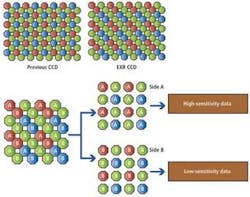
Rather than use a Bayer pattern to capture color images, Fujifilm has developed a technique known as close incline pixel coupling, which merges two adjacent pixels as one, forming a pseudo-Bayer pattern. However, because the area of imaging elements is doubled, so too is the sensitivity. Super CCD EXR devices are also capable of taking two exposures of the same scene at different exposure times to produce two images that are combined to create a high-dynamic-range image.
Future developments
While spatial approaches such as these have their benefits, other methods that remain mostly the subject of research have also been proposed. These include techniques such as time-to-saturation methods and locally adaptive techniques. Both of these methods, as in other types of techniques, add additional circuitry to each pixel element.
In time-to-saturation methods, for example, the dynamic range of each pixel is increased by simultaneously measuring the saturation level of each photodetector pixel and the time it will take for the pixel to saturate. By reading these two signal measurements in conjunction with each other, each photosite can be dynamically controlled to extend the dynamic range of the imager. In locally adaptive methods, local average pixel values are first estimated and then subtracted from each photosite to increase contrast and dynamic range.
While these methods may be the subject of ongoing research and patent applications, they may soon find their way into commercial imagers and cameras. What is more interesting, though, is how sensor vendors are incorporating multiple spatial and temporal techniques into their imagers to increase dynamic range of their current and future products.
Company Info
Awaiba, Madeira, Portugal
www.awaiba.com
Cypress Semiconductor
San Jose, CA, USA
www.cypress.com
Fujifilm, Tokyo, Japan
www.fujifilmusa.com
Gevitec, Ettlingen, Germany
www.gevitec.de
IMS Chips, Stuttgart, Germany
www.ims-chips.de
Melexis, Concord, NH, USA
www.melexis.com
Moscow Engineering Physics Institute, Moscow, Russia
www.mephi.ru
Panasonic, Osaka, Japan
www.panasonic.com
Photonfocus, Lachen, Switzerland
www.photonfocus.com